Accurate data-aided frequency tracking circuit

a data-aided frequency tracking and accurate technology, applied in the direction of digital transmission, amplitude demodulation, transmission, etc., can solve the problems of complex ml estimator computation, over-tasking, and inability to be properly don

Inactive Publication Date: 2009-05-21
DIGITALPTICS CORP INT
View PDF8 Cites 19 Cited by
  • Summary
  • Abstract
  • Description
  • Claims
  • Application Information

AI Technical Summary

Benefits of technology

[0045]For example, hardware for performing selected tasks according to embodiments of the invention could be implemented as a chip or a circuit. As software, selected tasks according to embodiments of the invention could be implemented as a plurality of software instructions being executed by a computer using any suitable operating system. In an exemplary embodiment of the invention, one or more tasks according to exemplary embodiments of method and/or system as described herei

Problems solved by technology

This frequency error, or offset, is due to inaccuracies in the LNB as well as the tuner, whose oscillators are not matched exactly to one another or for that matter to the transmitter's oscillato

Method used


Image

  • Accurate data-aided frequency tracking circuit
  • Accurate data-aided frequency tracking circuit
  • Accurate data-aided frequency tracking circuit

Examples


Embodiment Construction

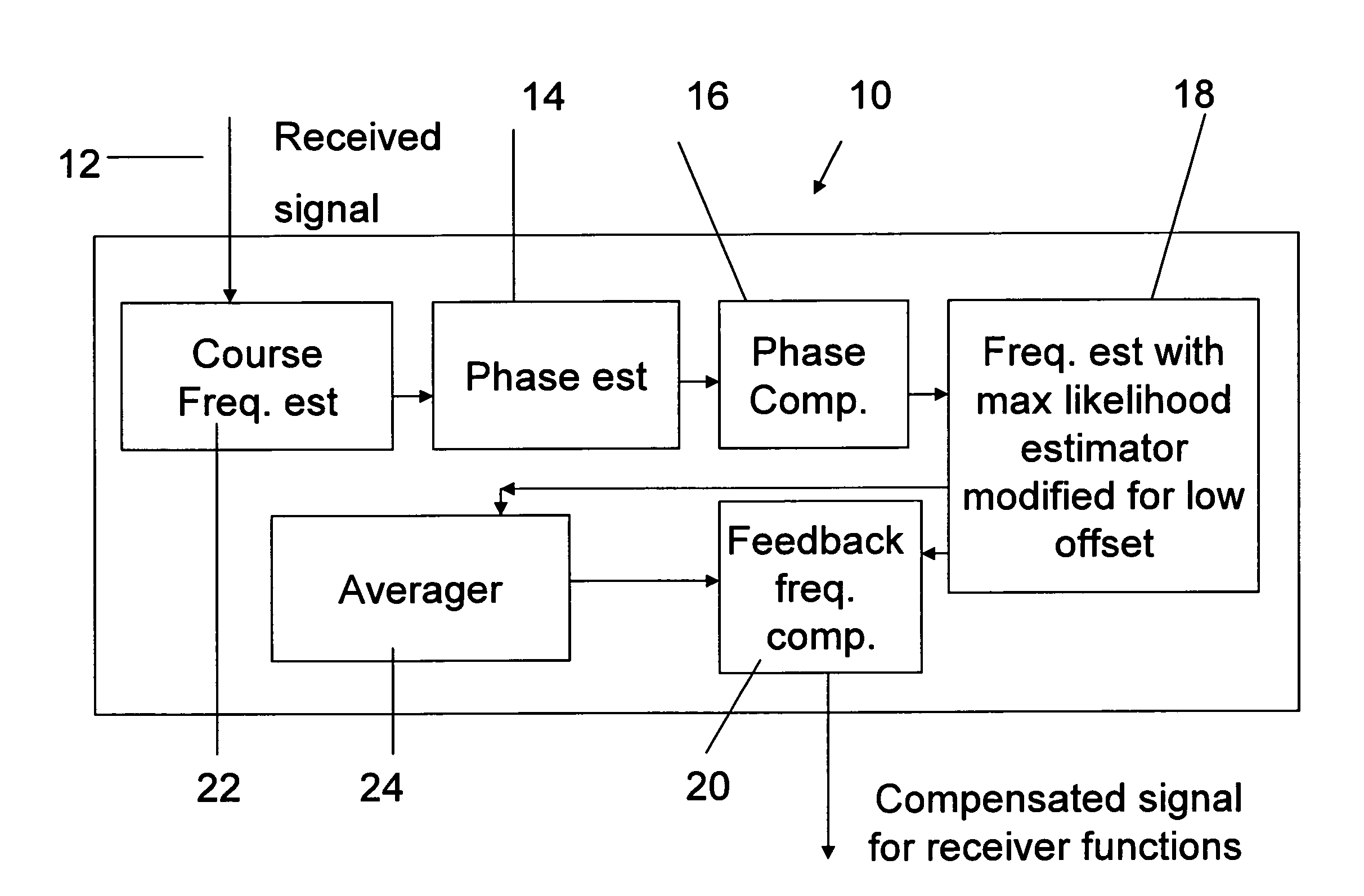
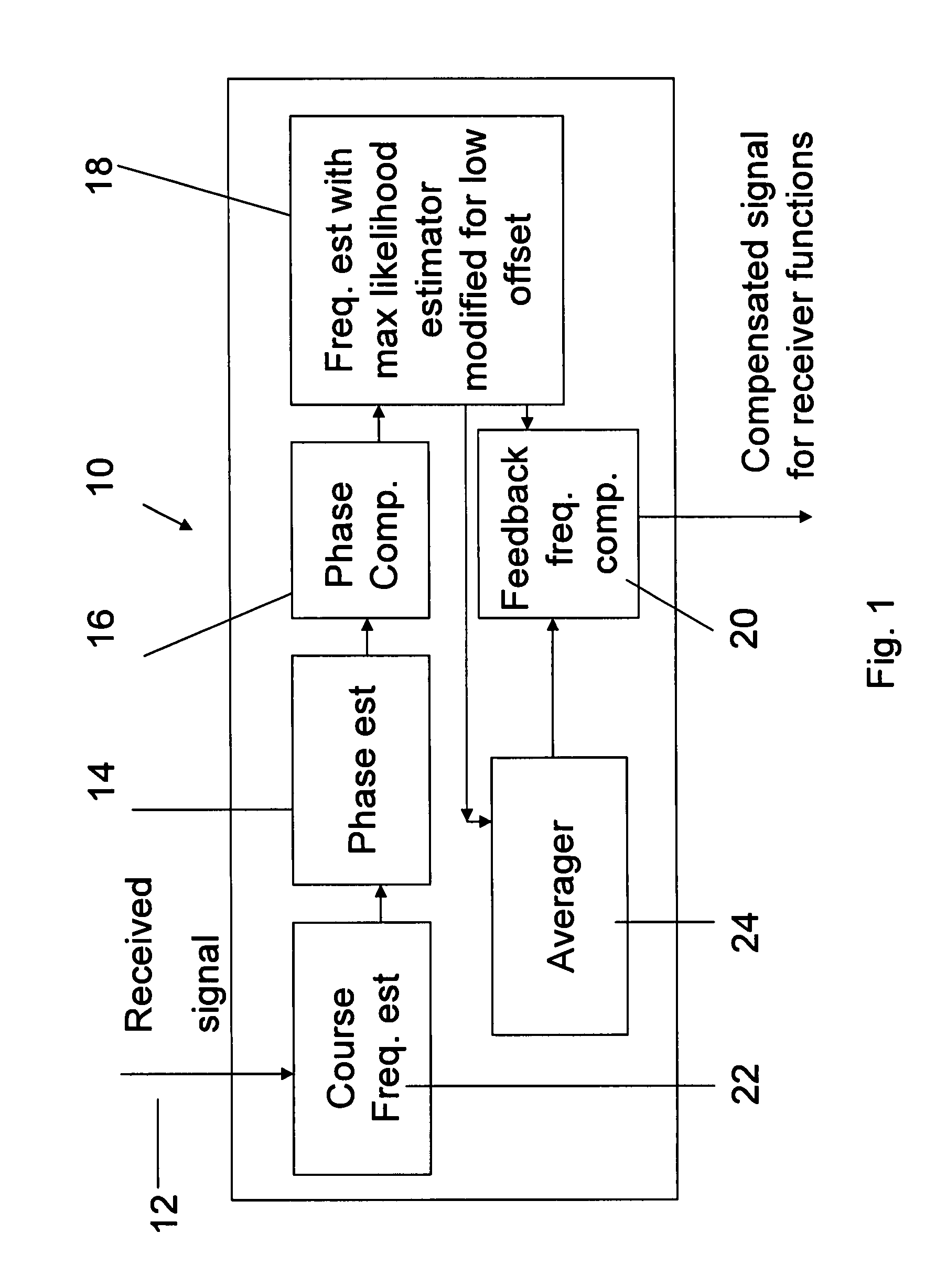
[0052]Preferred embodiments of the present invention relate principally to a situation in which the frequency offset at the input to a phase locked loop (PLL) is relatively small, say of the order of 10−3 of the symbol rate. While prior art systems adopt various methods and approximations to maximize {tilde over (Λ)}(f), the present embodiments take a different approach.

[0053]The above-mentioned offset, while small, is still large enough to overwhelm the PLL. In such a case one may first estimate and compensate for the phase of the signal. The resulting phase compensated signal may be passed through a modified maximum likelihood estimator to provide an estimate of the frequency offset. The estimation procedure above yields a biased estimator. The modified maximum likelihood estimator is based on an approximation valid when the frequency offset is small relative to the symbol rate, which is the situation described above. A derivation is provided below.

[0054]Before explaining at least...


PUM


Abstract

A frequency compensation circuit for compensating for a frequency offset in a received signal, the received signal including a periodically repeated pilot sequence for phase locking. The circuit comprises a phase estimator for estimating a phase of the received signal; a phase compensator, associated with the phase estimator, for compensating for the phase; a frequency estimator, comprising a maximum likelihood estimator comprising a first modification for estimating a frequency offset which is small relative to a symbol time, from the pilot sequence, the frequency estimator being connected downstream of the phase compensator; and a frequency compensator for applying a compensation to the signal, thereby to compensate for the frequency offset. The compensator is suitable for the exacting conditions of the DVB-S2 standard.

Description

FIELD AND BACKGROUND OF THE INVENTION[0001]The present invention, in some embodiments thereof, relates to an improved data-aided frequency tracking circuit and, more particularly, but not exclusively, to such circuits which use maximum likelihood estimations and a regularly repeated pilot signal for the frequency tracking. That is to say, the present invention is generally related to a carrier frequency estimation circuit for a digital demodulator operating on passband, digitally modulated signals, and a method of estimating the carrier frequency of the received data. More specifically, the present invention relates to carrier frequency estimation when known data is embedded in the transmitted signal.[0002]The purpose of digital communication is to deliver discreet data streams from one point to others. In order to achieve this purpose, a large variety of modulation methods have been developed over the years. Those methods can be conceptually divided into two categories: Baseband an...

Claims


Application Information

Patent Timeline
IPC IPC(8): H04L7/02H03D1/00H04L27/06
CPCH04L27/0014H04L2027/0026H04L2027/0095H04L2027/0067H04L2027/003
Inventor TWITTO, MOSHE
Owner DIGITALPTICS CORP INT
Why Eureka
Try Eureka