Band-gap reference source with high power supply restraint

A technology of high power supply suppression and reference source, which is applied in the direction of electrical components, adjusting electric variables, and electrical signal transmission systems, etc., can solve the problems of low precision and poor power supply suppression performance, and achieve a small circuit area, The current consumption is small, and the effect of normal operation is guaranteed

Inactive Publication Date: 2008-02-27
HUAZHONG UNIV OF SCI & TECH
View PDF0 Cites 39 Cited by
  • Summary
  • Abstract
  • Description
  • Claims
  • Application Information

AI Technical Summary

Problems solved by technology

The circuit structure of the traditional bandgap reference source is shown in Figure (1). Its power supply rejection performa

Method used


Image

  • Band-gap reference source with high power supply restraint
  • Band-gap reference source with high power supply restraint
  • Band-gap reference source with high power supply restraint

Examples


Embodiment Construction

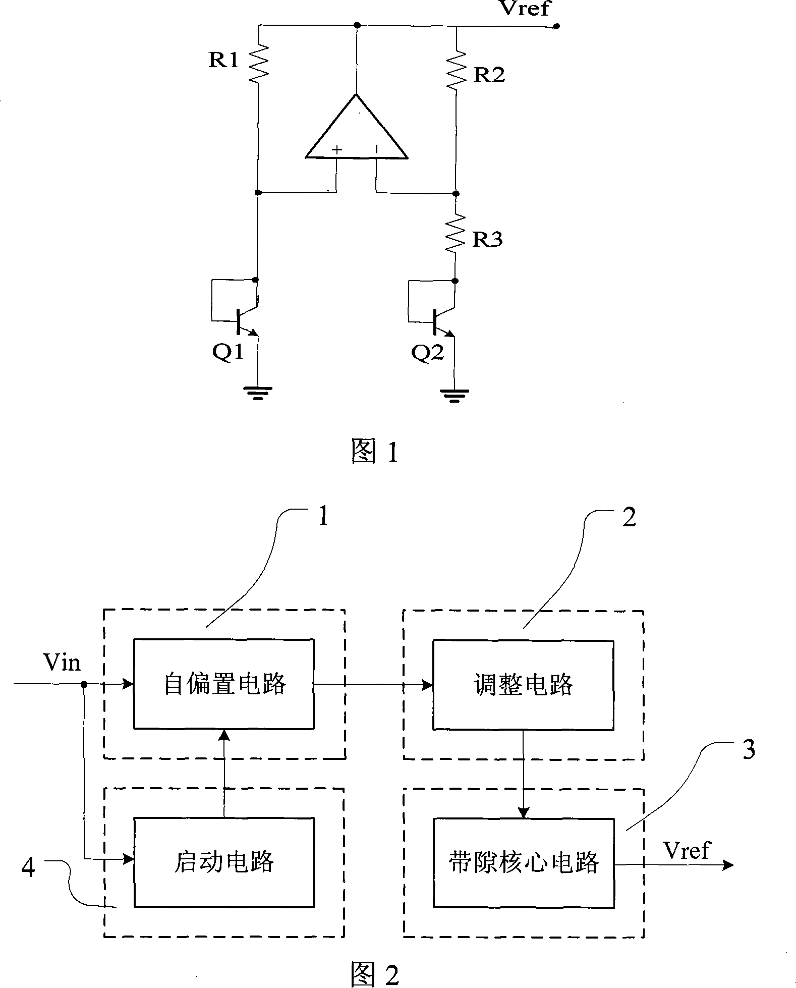
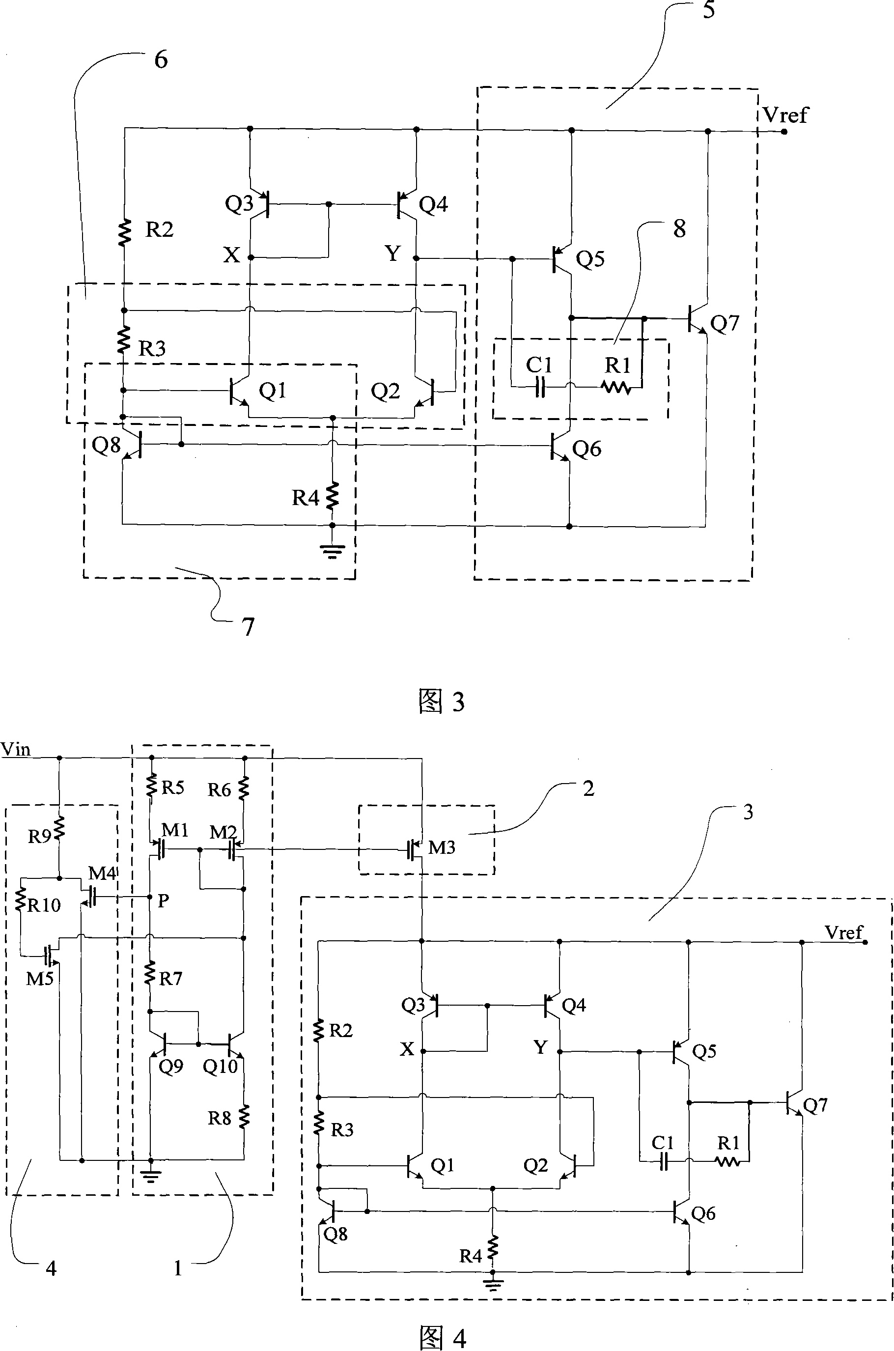
[0017] The invention is a bandgap reference source with a start-up circuit and a self-bias circuit, which has the advantages of high power supply rejection (PSRR), large input range, small voltage adjustment rate, and low current consumption under the same power supply voltage. As shown in FIG. 2 , the bandgap reference source includes a bandgap core circuit 3 for generating a reference, a self-bias circuit 1 , an adjustment circuit 2 and a start-up circuit 4 for providing external power to the bandgap core circuit 3 . When the supply voltage V IN When powered on, the start-up circuit 4 works to drive the self-bias circuit 1 to turn on; after the self-bias circuit 1 is turned on, the start-up circuit 4 is turned off, and provides a relative power supply voltage V for the adjustment circuit 2 through its own bias. IN irrelevant bias voltage; the adjustment circuit 2 provides an external power supply independent of the power supply voltage for the bandgap core circuit 3; the ban...


PUM


Abstract

There is a sort of reference source which has the crack by checking the high electrical source, and it consists of the self-polarization circuit, the regulating circuit, the kernel circuit which has the crack, and the startup circuit. The IPTAT generating circuit of the kernel circuit which has the crack makes the collector current of the Q1 and Q2 of the NPN pipe to equal by that the degenerative feedback which is magnified adjusts its quiescent point, the IPTAT current and the VBE of the Q8 of the NPN transistor which has the negative temperature coefficient in the constant-current circuit are progressed the first compensation of the temperature, at the same time they debase the temperature coefficient. The constant-current circuit produces the polarization by itself, and provides the polarization current to the IPTAT generating current. The operational amplifier circuit advances the plus for the two-stage operational amplifier, the compensation current progresses the frequency compensation for the two-stage operational amplifier. The generating circuit removes the dependency of the reference export VREF to supply voltage by negative feedback effect in order advance the PSRR. The startup circuit removes the degeneration polarization point and it drives the self-polarization circuit to work. The self-polarization circuit provides the polarization voltage for the regulating circuit. The circuit configuration of this invention is simple and new, it does not need the external polarization, the area of this circuit is small, and it has the good temperature coefficient.

Description

technical field [0001] The invention belongs to the field of digital-analog hybrid integrated circuits, specifically a Bi-CMOS bandgap reference source with low power consumption and high power supply rejection, which is a bandgap reference voltage source with simple structure, low power consumption and high power supply rejection ratio, and is especially suitable for application In the analog / digital converter (ADC) and digital / analog converter (DAC) of hybrid integrated circuits. Background technique [0002] In the design of ADC and DAC hybrid integrated circuits, the high-performance reference source (Reference) integrated on-chip is indispensable. With the complexity of the circuit system and the refinement of the digital-analog mixed signal, the requirements for hybrid integrated circuits such as ADC and DAC are getting higher and higher, so the requirements for the reference source, especially its power supply suppression, are also getting higher and higher. . [00...

Claims


Application Information

Patent Timeline
IPC IPC(8): G05F3/24H03M1/34H03M1/66
Inventor 邹雪城陈晓飞刘占领雷鑑铭刘政林郑朝霞
Owner HUAZHONG UNIV OF SCI & TECH
Why Eureka
Try Eureka