Determination of a code phase

a code phase and phase determination technology, applied in the field ofsignal acquisition modules, can solve the problems of code doppler compensation no longer correct, dft bank b>15/b> cannot check the whole uncertainty range, and may be so large in the combined uncertainty range, so as to improve the sensitivity of the architecture, prolong the integration time, and increase the frequency uncertainty

Inactive Publication Date: 2006-06-22
NOKIA TECHNOLOGLES OY
View PDF5 Cites 40 Cited by
  • Summary
  • Abstract
  • Description
  • Claims
  • Application Information

AI Technical Summary

Benefits of technology

[0028] It is an advantage of the invention that it enables longer integration times. This implies a better sensitivity of the architecture and a toleration of more frequency uncertainty.
[0029] It is further an advantage of the invention that a simple memory addressing is used for achieving the compensation effect. No extra hardware delay lines or filters are needed.
[0030] For a first aspect of the invention, a signal acquisition module for determining a correct code phase of a received, code modulated carrier signal is proposed. The proposed signal acquisition module comprises a correlation portion adapted to provide correlation values for different possible code phase offsets between a received, code modulated carrier signal and an available replica code sequence. The proposed signal acquisition module further comprises a frequency compensation portion adapted to compensate in correlation values output by the correlation portion a plurality of possible frequency offsets. The proposed signal acquisition module further comprises a coherent memory adapted to coherently accumulate during a respective coherent integration cycle correlation values provided by the frequency compensation portion for a respective combination of a specific code phase and a specific frequency compensation. The proposed signal acquisition module further comprises a non-coherent memory adapted to non-coherently accumulate during a non-coherent integration cycle correlation values accumulated in a respective completed coherent integration cycle in the coherent memory for a respective combination of a specific code phase and a specific frequency compensation. The proposed signal acquisition module further comprises a mapping portion adapted to map a correlation value which is to be added to one of the coherent memory and the non-coherent memory to a respective position in the memory, which position is associated to a combination of a specific code phase and a specific frequency compensation, and which position is adjusted depending on at least one of a frequency compensation applied by the frequency compensation portion in combination with elapsed integration time, and on a drift of a frequency offset in correlation values output by the correlation portion.

Problems solved by technology

The combined uncertainty may be so large that the DFT bank 15 is not able to check the whole uncertainty range with a single search.
It is a disadvantage of the signal acquisition module described with reference to FIG. 1 that the DFT bank 15 compensates only for the carrier Doppler effect, not the code Doppler effect.
But if the signal is in one of the outermost DFT bins, the code Doppler compensation is no longer correct, and the signal will slide over several code phase bins during the searc

Method used


Image

  • Determination of a code phase
  • Determination of a code phase
  • Determination of a code phase

Examples


first embodiment

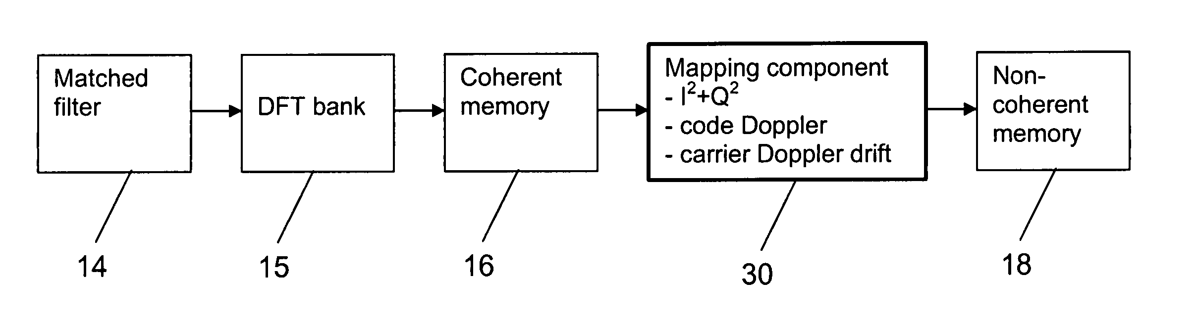
[0064] the signal acquisition module 22 according to the invention is presented in FIG. 3. It is a modification of the known signal acquisition module presented with reference to FIG. 1.

[0065] The signal acquisition module 22 comprises again a mixer and a decimation block (not shown), a matched filter 14, a DFT bank 15 and a coherent memory 16. The coherent memory 16 is structured again in the form of a table which comprises one column for a respective code phase bin and one row for a respective DFT bin. The signal acquisition module 22 also comprises a non-coherent memory 18, which is structured again in the same way as the coherent memory 16.

[0066] In contrast to FIG. 1, however, a mapping component 30 is inserted between the coherent memory 16 and the non-coherent memory. The function of the processing component 17 of the signal acquisition module of FIG. 1 is integrated by way of example in this mapping component 30.

[0067] The mapping component 30 comprises in addition a porti...

second embodiment

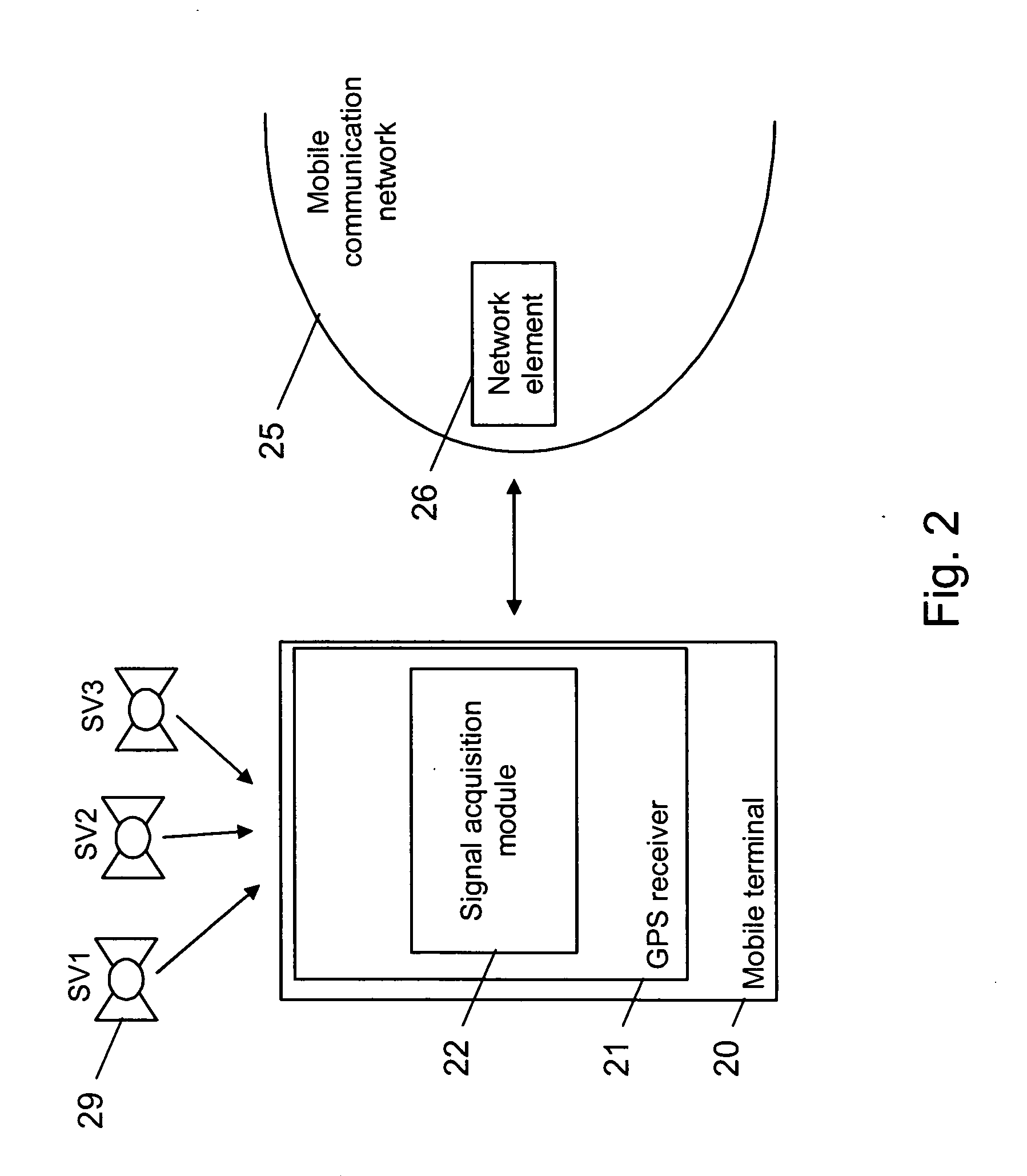
[0100]FIG. 9 presents the signal acquisition module 22 of the GPS receiver 21 in FIG. 2. Also this embodiment is a modification of the signal acquisition module presented with reference to FIG. 1.

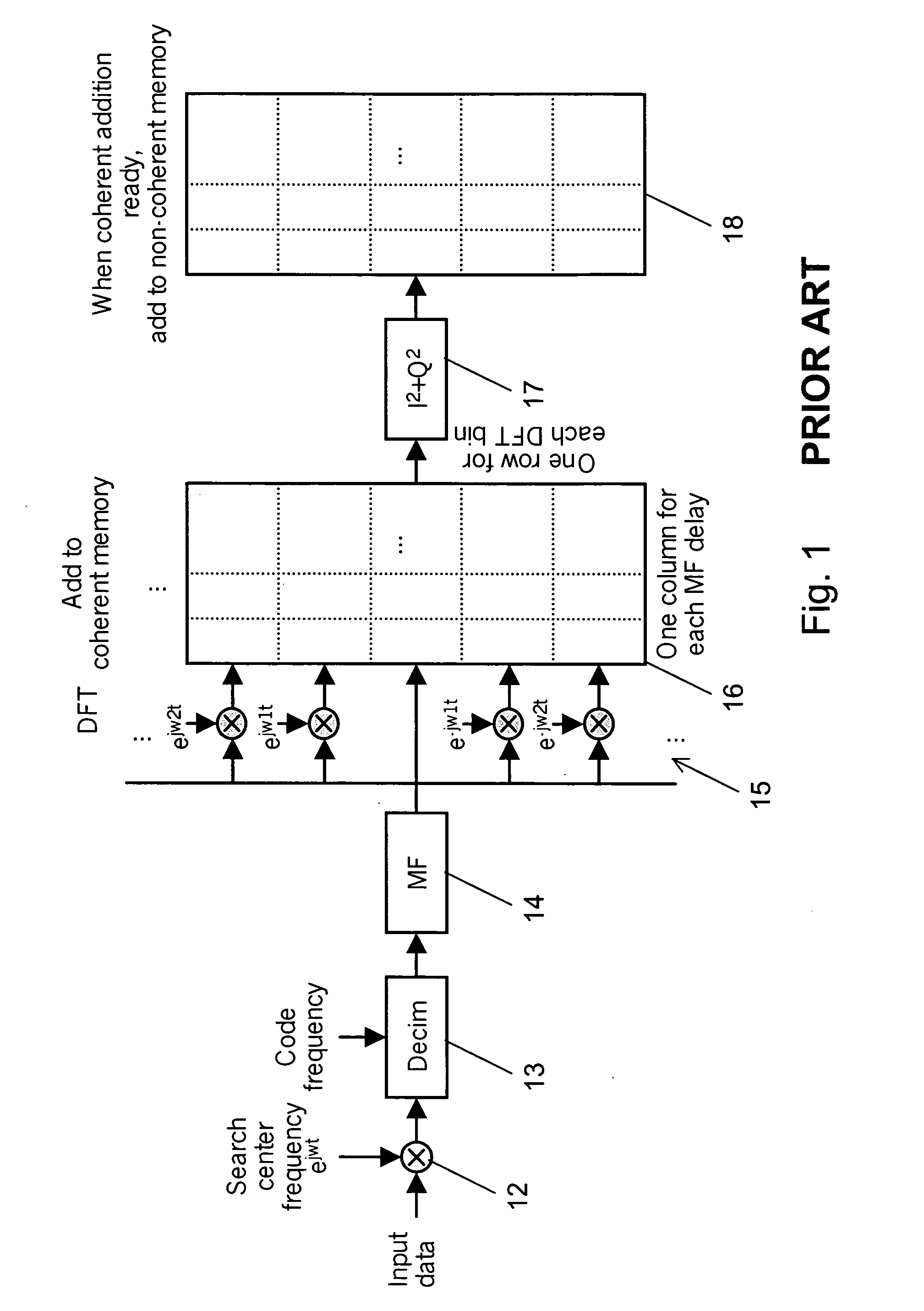
[0101] The signal acquisition module 22 comprises a mixer and a decimation block (not shown), a matched filter 14, a DFT bank 15, a coherent memory 16, a processing component 17 and a non-coherent memory 18. Both memories 16, 18 are structured in the same way as the memories 16, 18 in FIGS. 1 and 3.

[0102] In contrast to FIG. 1, however, a mapping component 90 is inserted between the DFT bank 15 and the coherent memory 16. The mapping component 90 realizes a code Doppler compensation and a carrier Doppler drift compensation.

[0103] The operation of this signal acquisition module 22 is the same as illustrated in FIG. 4, except that the order of processing is changed. More specifically, the code Doppler compensation in step 408 and the possible carrier Doppler drift compensation in step 409 a...

fourth embodiment

[0106]FIG. 10 presents a third and fourth embodiment of the signal acquisition module 22 of the GPS receiver 21 in FIG. 2. Also these embodiments are modifications of the signal acquisition module presented with reference to FIG. 1.

[0107] The signal acquisition module 22 comprises again a mixer and a decimation block (not shown), a matched filter 14, a DFT bank 15, a coherent memory 16, a processing component 17 and a non-coherent memory 18. Both memories 16, 18 are structured in the same way as the memories 16, 18 in FIG. 1.

[0108] In contrast to FIG. 1, however, a mapping component 100 has access either to the coherent memory 16 or to the non-coherent memory 18, the latter alternative being indicated in FIG. 10 by dashed lines. The mapping component 100 realizes a code Doppler compensation and a carrier Doppler drift compensation in accordance with the invention.

[0109] If the mapping component 100 has access to the coherent memory 16, the operation of the signal acquisition modul...


PUM


Abstract

The invention relates to determining a correct code phase of a received, code modulated carrier signal using a correlation portion, a frequency compensation portion, a coherent memory and a non-coherent memory. In order to compensate for a code Doppler effect and/or a carrier Doppler drift effect, a mapping portion maps correlation values either to the coherent memory or to the non-coherent memory. Alternatively, the mapping portion maps correlation values stored in the coherent memory or in the non-coherent memory to new positions. The mapping depends on a frequency compensation applied by the frequency compensation portion and elapsed integration time, and/or on a drift of a frequency offset in correlation values output by said correlation portion.

Description

FIELD OF THE INVENTION [0001] The invention relates to signal acquisition modules, electronic devices, systems, methods and software program products for determining a correct code phase of a received, code modulated carrier signal. BACKGROUND OF THE INVENTION [0002] The code phase of a received, code modulated carrier signal has to be determined for example in CDMA (Code Division Multiple Access) spread spectrum communications. [0003] For a spread spectrum communication in its basic form, a data sequence is used by a transmitting unit to modulate a sinusoidal carrier, and then the bandwidth of the resulting signal is spread to a much larger value. For spreading the bandwidth, the single-frequency carrier can be multiplied for example by a high-rate binary pseudo-random noise (PRN) code sequence comprising values of −1 and 1, which code sequence is known to a receiver. Thus, the signal that is transmitted includes a data component, a PRN component, and a sinusoidal carrier component...

Claims


Application Information

Patent Timeline
IPC IPC(8): H04B1/707
CPCG01S19/29G01S19/30H04B1/708H04B1/7097
Inventor PIETILA, SAMULIVALIO, HARRI
Owner NOKIA TECHNOLOGLES OY
Why Eureka
Try Eureka