Image generating apparatus and calibration method therefor

a technology of image generating apparatus and calibration method, which is applied in the direction of electrographic process apparatus, instruments, printing, etc., can solve the problems of high cost, inability to change the amount of correction measured at the factory for and render the cost reduction of the image generating apparatus meaningless, etc., to achieve simple procedures and correct the degradation of image quality

Active Publication Date: 2009-05-21
CANON KK
View PDF4 Cites 12 Cited by
  • Summary
  • Abstract
  • Description
  • Claims
  • Application Information

AI Technical Summary

Benefits of technology

[0009]The present invention has been made in view of the conventional example described above and provides an optical scanning, electrophotographic image generating apparatus which ca

Problems solved by technology

However, the amounts of correction measured at the factory for the image generating apparatus can change if optical parts are worn or torn over time or replaced due to a failure.
This is done i

Method used


Image

  • Image generating apparatus and calibration method therefor
  • Image generating apparatus and calibration method therefor
  • Image generating apparatus and calibration method therefor

Examples


first embodiment

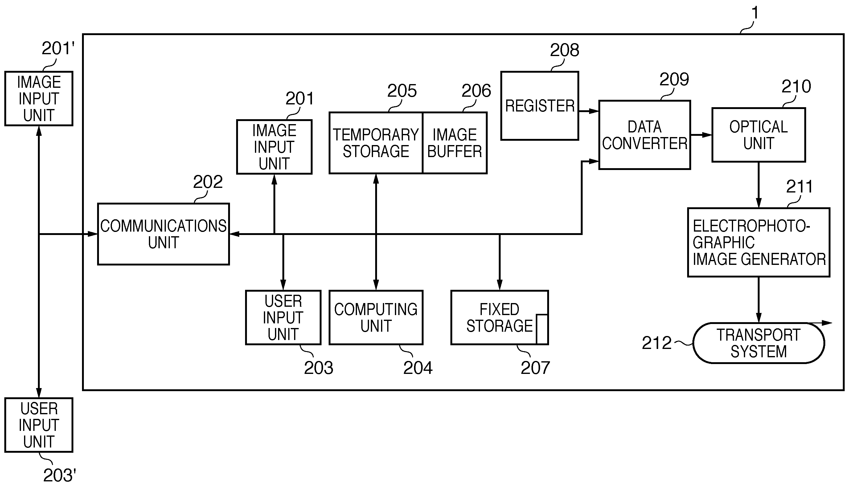
[0040]FIG. 3 is a block diagram showing a digital multi function peripheral 1 according to an embodiment of the present invention, where the digital multi function peripheral 1 is a color image generating apparatus and will be referred to hereinafter as a multicolor printing apparatus. In FIG. 3, image input units 201 and 201′ are, for example, image scanners. When the multicolor printing apparatus is a printer there is no such component as an image input unit 201. The image input units 201 and 201′ are sometimes connected as external apparatus via an interface. A communications unit 202 is, for example, a LAN interface and serves as a means of communications with external apparatus. The communications unit 202 receives print information from an external apparatus, receives image data from external image input units, and transmits and receives data to change operation mode based on commands from a user input unit on an external apparatus. A user input unit 203 is, for example, an op...

second embodiment

[0077]Depending on the configuration of the multicolor printing apparatus, most parts of data processing are performed by software running on an external apparatus. An example is shown in FIG. 5. Built-in functions of a multicolor printing apparatus 1′ include a communications unit 202 used for communications with an external apparatus 230, an input / output buffer (image buffer) 206, a console (not shown), and a small-scale controller 220 for use to drive mechanical parts of the multicolor printing apparatus according to predetermined procedures. The input / output buffer (image buffer) 206 is intended to absorb instability during communications. The console is used by the operator to input commands. The controller 220 includes a status reader which reads status detected by a sensor or the like. Mechanical parts include an optical unit 210, electrophotographic image generator 211, and transport system 212. In this configuration, skew correction and other image processing as a whole are...

third embodiment

[0088]Depending on paper feed accuracy of a paper transport mechanism of the multicolor printing apparatus, the transport mechanism may transport printing paper in an inclined state instead of transporting it accurately. In the case of new printing on unpatterned paper, a slight inclination does not present practical problems, but when a plurality of printed patterns are handled as with the calibration procedures according to the present invention, even a very small inclination poses a problem. Depending on the inclination, it becomes difficult to accurately read an amount of skew caused by optical distortion of optical scanning.

[0089]Thus, according to the present embodiment, a detection pattern is added to the correction pattern and adjustment pattern to detect transport skew. When transport skew is detected, calibration procedures are carried out anew.

[0090]FIG. 7 shows a correction pattern to which an inclination reference pattern 110 has been added to detect transport skew whil...


PUM


Abstract

To correct distortion in an optical system of an optical scanning, electrophotographic image generating apparatus, a parallel line group 107′ is printed by a printing apparatus to be calibrated on a sheet on which a correction pattern 101 has been printed. The user reads marker positions to find amounts of deviation of the adjustment pattern from the correction pattern and inputs the amounts of deviation in the printing apparatus. The printing apparatus interpolates values between the input amounts of deviation, establishes positions at which a line in the adjustment pattern deviate one pixel in a sub-scanning direction as scan line changing points and generate new conversion information by pairing the scan line changing points with respective directions of deviation. During image generation, the printing apparatus prints an image by correcting image data according to the conversion information.

Description

BACKGROUND OF THE INVENTION[0001]1. Field of the Invention[0002]The present invention relates to an electrophotographic image generating apparatus which generates an image by scanning a photosensitive member with an optical beam and to a calibration method therefor.[0003]2. Description of the Related Art[0004]An optical scanning, electrophotographic image generating apparatus forms a latent image on a photosensitive member by optical drawing, develops the latent image with toner, transfers a resulting toner image to paper, fixes the toner image, and thereby produces a printout.[0005]Basically, the optical scanning image generating apparatus has a single light source. However, to produce a printout at high speed using a low-speed device, a number of light sources are used in parallel in a single optical system. This reduces operating frequencies of an electronic circuit's drive unit and a processing system. In the case of color image generation, the image generating apparatus has as ...

Claims


Application Information

Patent Timeline
IPC IPC(8): G03G15/00
CPCG03G15/50G03G15/043
Inventor SHOJI, ATSUSHI
Owner CANON KK
Why Eureka
Try Eureka