Fuel Cell System and Operation Method Thereof

a fuel cell and system technology, applied in the field of fuel cell systems, can solve the problems of reducing the heat resistance reducing the service life of ion exchange resins, so as to effectively restrict the propagation of bacteria in water

Inactive Publication Date: 2009-05-21
PANASONIC CORP
View PDF1 Cites 27 Cited by
  • Summary
  • Abstract
  • Description
  • Claims
  • Application Information

AI Technical Summary

Benefits of technology

[0046]The fuel cell systems according to the embodiments of the invention are capable of effectively restraining the propagation of bacteria in the water by means of a simple arrangement while the power generating operation of the fuel cell system is stopped so that there is unlikely to occur damage to its water feeding function and water purifying function.

Problems solved by technology

However, there is a problem that most of the ion exchange resins that can be used for the water purifier are comparatively low in heat resistance.
This problem is significant particularly where a minus ion exchange resin is used as the ion exchange resin.
If the temperature of the cooling water supplied to the water purifier by the pump exceeds the allowable temperature limit of the ion exchange resin, the degradation of the ion exchange resin due to heat escalates, shortening the service life of the ion exchange resin.

Method used


Image

  • Fuel Cell System and Operation Method Thereof
  • Fuel Cell System and Operation Method Thereof
  • Fuel Cell System and Operation Method Thereof

Examples


first embodiment

[0087]First of all, the structure of a fuel cell system according to a first embodiment of the invention will be explained in detail with reference to the drawings.

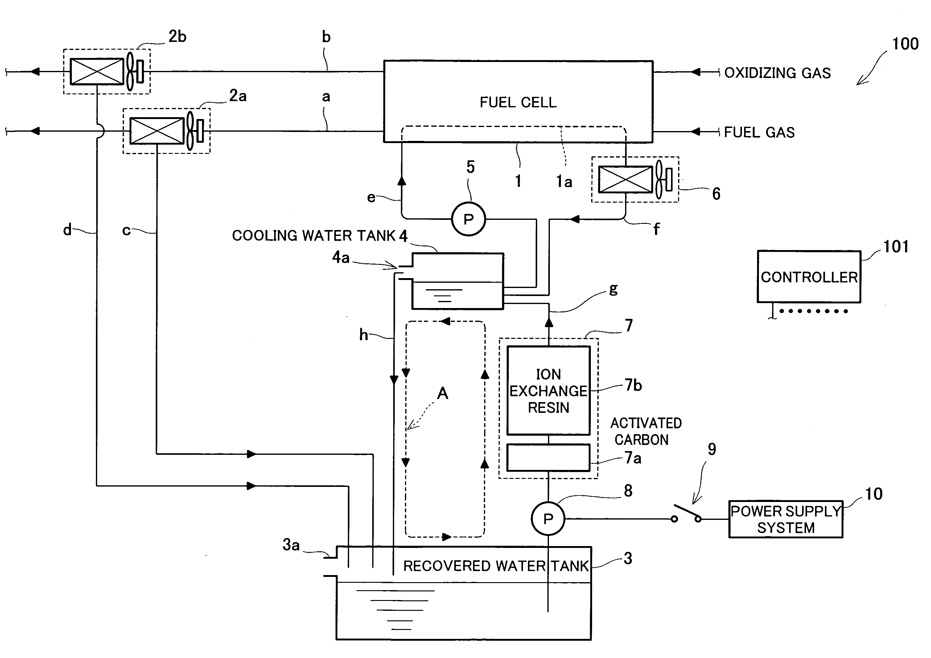
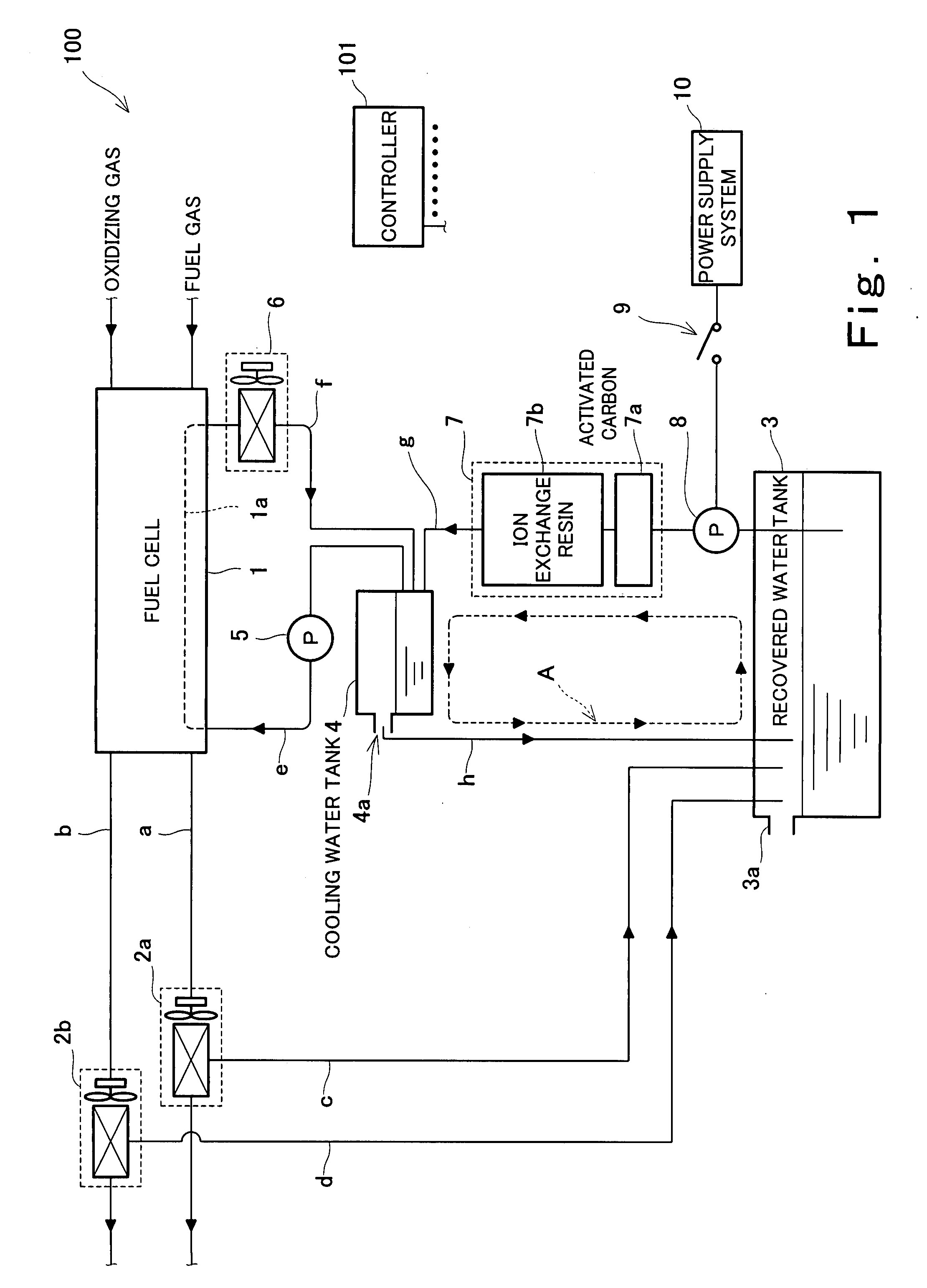
[0088]FIG. 1 is a block diagram schematically illustrating the structure of the fuel cell system according to the first embodiment of the invention. In FIG. 1, the solid lines connecting the elements that constitute the fuel cell system respectively designate a passage where water, a fuel gas, an oxidizing gas or the like flows. The arrows provided for the solid lines designate the flowing direction of the water, the fuel gas, the oxidizing gas or the like during normal operation. It should be noted that FIG. 1 shows only the elements indispensable for an explanation of the invention and other elements are omitted from the drawing.

[0089]As shown in FIG. 1, the fuel cell system 100 of the first embodiment has a fuel cell 1 as the main body of its power generating section. As the fuel cell 1, a proton-exchange membrane fuel...

second embodiment

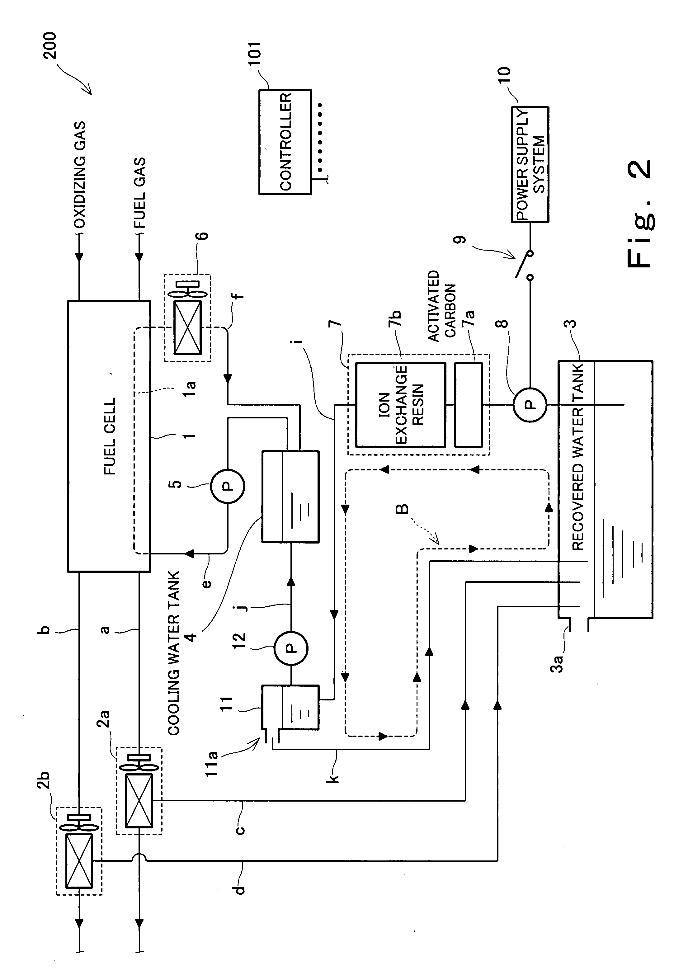
[0130]FIG. 2 is a block diagram schematically illustrating the structure of a fuel cell system according to a second embodiment of the invention. In FIG. 2, the solid lines connecting the elements that constitute the fuel cell system respectively designate a passage where water, the fuel gas, the oxidizing gas or the like flows. The arrows provided for the solid lines designate the flowing direction of the water, the fuel gas, the oxidizing gas or the like during normal operation. It should be noted that FIG. 2 shows only the elements indispensable for an explanation of the invention and other elements are omitted from the drawing. In FIG. 2, those parts that correspond to the elements of the fuel cell system 100 of the first embodiment are identified by the same reference numerals.

[0131]As shown in FIG. 2, the fuel cell system 200 of the second embodiment has a structure substantially similar to that of the fuel cell system 100 of the first embodiment. However, the fuel cell system...

third embodiment

[0137]FIG. 3 is a block diagram schematically illustrating the structure of a fuel cell system according to a third embodiment of the invention. In FIG. 3, the solid lines connecting the elements that constitute the fuel cell system respectively designate a passage where water, a fuel gas, an oxidizing gas or the like flows. The arrows provided for the solid lines designate the flowing direction of the water, the fuel gas, the oxidizing gas or the like during normal operation. It should be noted that FIG. 3 shows only the elements indispensable for an explanation of the invention and other elements are omitted from the drawing. In FIG. 3, those parts that correspond to the elements of the fuel cell systems 100, 200 of the first and second embodiments are identified by the same reference numerals.

[0138]As shown in FIG. 3, the fuel cell system 300 of the third embodiment has a structure substantially similar to that of the fuel cell system 200 of the second embodiment, including the p...


PUM

PropertyMeasurementUnit
temperatureaaaaaaaaaa

Abstract

A fuel cell system (100) comprising: a fuel cell (1) configured to generate electric power using an oxidizing gas and a fuel gas; a recovered water tank (3) configured to store water recovered from an exhaust gas discharged from the fuel cell; a water storage tank (4) configured to store water used as cooling water for cooling the fuel cell; a water feed flow path (g) through which the water stored in the recovered water tank is supplied to the water storage tank; a pump (8) configured to force water to flow from the recovered water tank to the water storage tank within the water feed flow path; a water purifier (7) configured to purify the water forcibly flowed by said pump in the water feed flow path by means of a built-in TOC absorber (7a) before the water is supplied to the water storage tank; and a controller (101), wherein the controller controls the pump so as to operate in a stop period of the fuel cell system such that water moves in the water feed flow path.

Description

TECHNICAL FIELD[0001]The present invention relates to fuel cell systems that are supplied with hydrogen and oxygen to generate electric power while the fuel cell being cooled by cooling water.BACKGROUND ART[0002]Fuel cell systems capable of high-efficiency, small-scaled power generation have been heretofore developed as distributed power generation equipment having high energy utilization efficiency. A primary reason for this is that a system for utilizing heat energy generated when the fuel cell systems generate electric power is easy to construct.[0003]A fuel cell system has a fuel cell as the main body of its power generating section. The fuel cell is an electric cell that directly converts the chemical energy of a fuel (hydrogen) and an oxidant (oxygen) into electric energy through a specified electrochemical reaction. Therefore, in a fuel cell system, the fuel cell is supplied with hydrogen serving as a fuel and oxygen serving as an oxidant during power generation. In the fuel ...

Claims


Application Information

Patent Timeline
Patent Type & Authority Applications(United States)
IPC IPC(8): H01M8/04
CPCH01M8/04029H01M8/04044Y02E60/50H01M8/04291H01M8/04164
Inventor YAMAMOTO, MASAOOZEKI, MASATAKA
Owner PANASONIC CORP
Why Eureka
Try Eureka