
High Speed Backplane Connector

a backplane connector and high-speed technology, applied in the direction of coupling contact members, coupling device connections, electrical apparatus, etc., can solve the problems of limiting performance and still exist alignment problems, and achieve the effect of low normal force and long-term fretting corrosion effects

Inactive Publication Date: 2009-05-21
TE CONNECTIVITY CORP
View PDF7 Cites 33 Cited by
  • Summary
  • Abstract
  • Description
  • Claims
  • Application Information

AI Technical Summary

Benefits of technology

[0007]An advantage of the present invention is that the mesh contact member provides alignment and signal continuity between printed circuit boards, particularly when exposed to rugged and / or extreme environmental conditions.
[0008]Another advantage of the present invention is that the mesh contact member can be formed with multitude of small wires and therefore low normal force between wire and socket providing an advantage of long-term fretting corrosion effects.
[0009]Another advantage of the present invention is that the mesh contact member can be soldered or welded at the tip therefore each wire is protected when misalignment of connector may otherwise cause damage to the contact interfaces as seen in many other designs.
[0010]Another advantage of the present invention is that the mesh contact portion can be protected by tightly controlled recessed cavity.

Problems solved by technology

Electronic equipment, such as that used in military applications, is often required to be operated in rugged, extreme environmental conditions.
Examples of such conditions include excessive moisture, salt, heat, vibration, mechanical shock, and electromagnetic interference.
While the flex circuits may provide easier access for the soldering, problems with alignment still exist.
In addition, the flex circuit has long tails that act like antennae, which tails create interference and limit performance as described above.

Method used


Image

  • High Speed Backplane Connector
  • High Speed Backplane Connector
  • High Speed Backplane Connector

Examples


Embodiment Construction

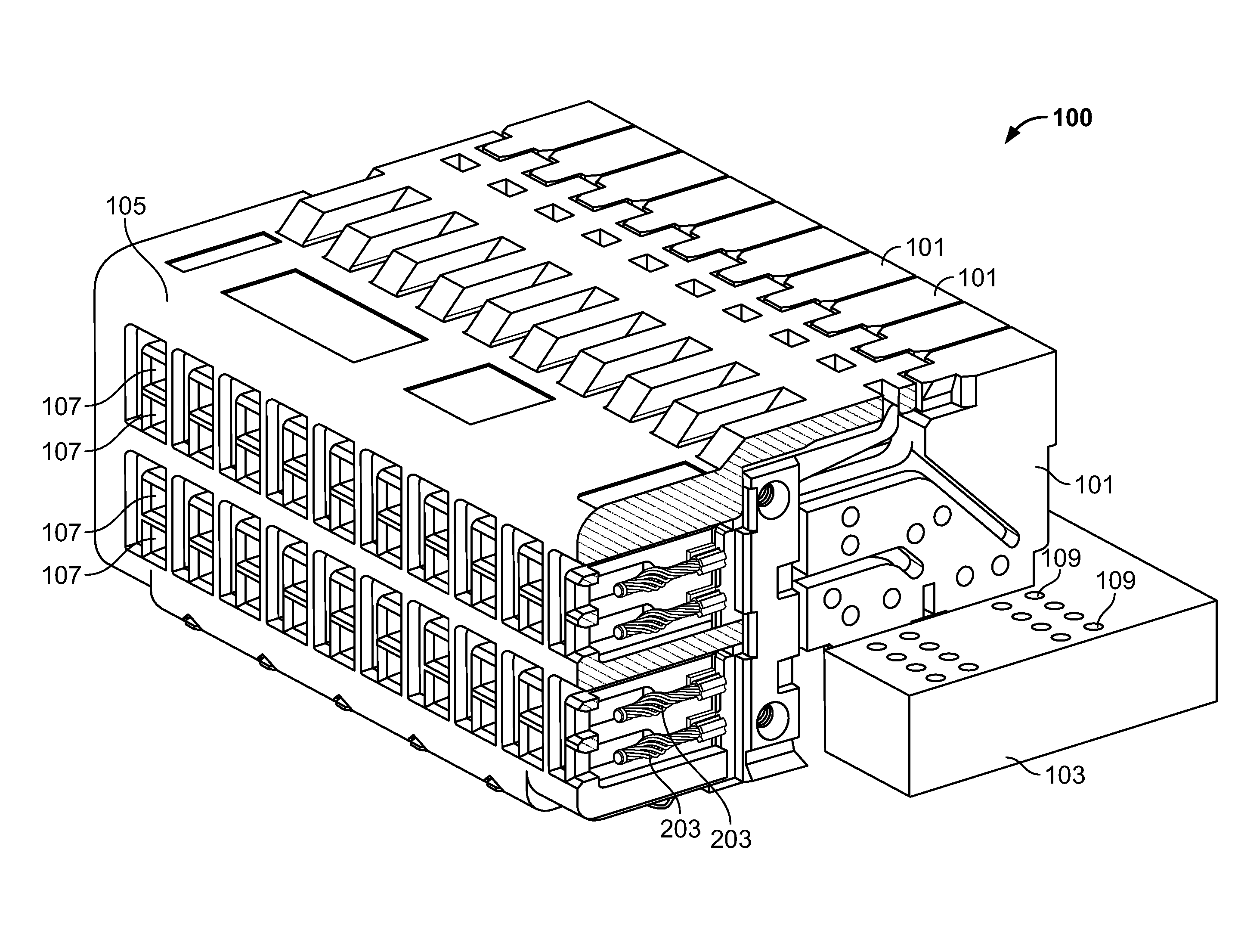
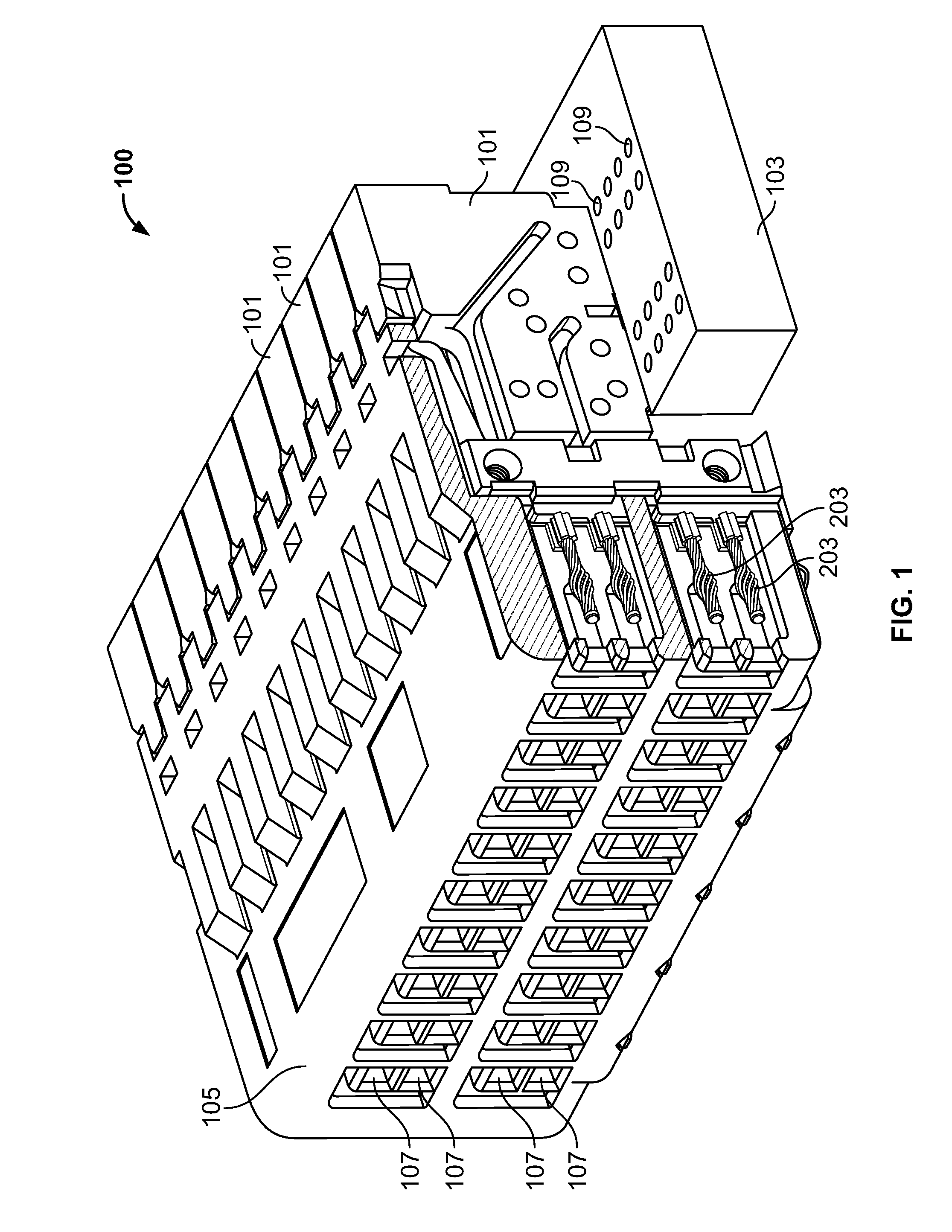
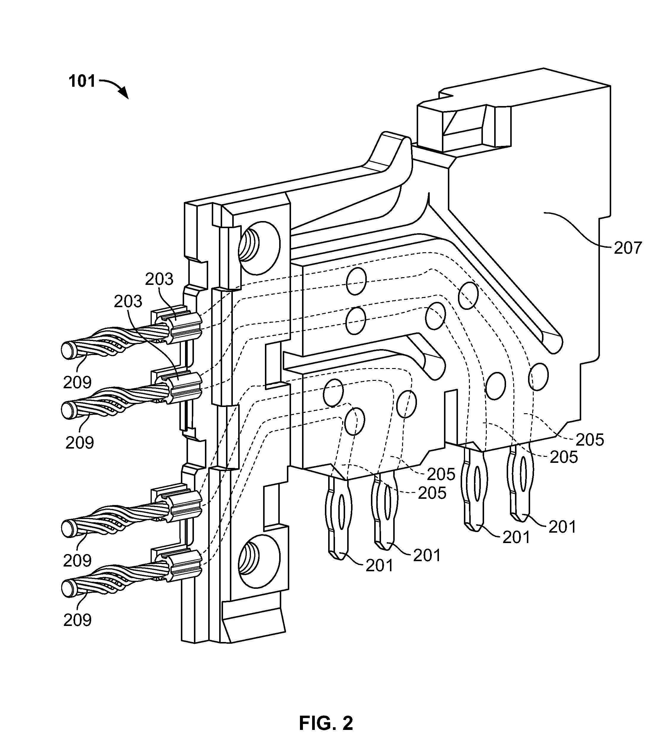
[0019]FIG. 1 shows a connector system 100 according to an embodiment of the disclosure including a plurality of terminal modules 101 connected to a printed circuit board (PCB) 103 and inserted into a terminal housing module 105. Housing module 105 includes a plurality of socket receiving apertures 107 configured to receive sockets of a backplane 400 (see e.g. FIGS. 4-5). The terminal modules 101 connect to the PCB 103 via first contact portion 201 (see e.g., FIG. 2) engaged with opening 109 in the PCB 103. The terminal modules 101 include second contact portions 203 (see also e.g., FIG. 2) for connecting to a backplane 400 (see e.g., FIGS. 4-5). Shielding members 111 are configured and disposed adjacent terminal modules 101 to provide shielding for the second contact portions 201 (see e.g., FIG. 6). Shielding members 111 or similar structures may be utilized to shield the signal contacts from EMI / RFI.

[0020]FIG. 2 shows a perspective view of a terminal module 101 according to an embo...


PUM


Abstract

A terminal module for assembly into a high speed electrical connector. The module includes an electrically insulated housing, a first contact portion and a second contact portion. The second contact portion is in electrical communication with the first contact portion via a contact interconnection. The contact interconnection is at least partially disposed within the insulated housing. At least one of the first contact portion or the second contact portion includes a contact selected from the group consisting of a mesh contact element, a socket configured to receive a mesh contact element and combinations thereof.

Description

FIELD OF THE INVENTION[0001]The present disclosure is directed to electrical connectors. In particular, the disclosure is directed to high speed electrical connectors for connecting circuit boards for harsh vibration environment applications such as military and aero space.BACKGROUND OF THE INVENTION[0002]Electronic equipment, such as that used in military applications, is often required to be operated in rugged, extreme environmental conditions. Examples of such conditions include excessive moisture, salt, heat, vibration, mechanical shock, and electromagnetic interference. To function cooperatively, some type of connector is required so that when two printed circuit boards are brought into electrical contact with one another, the boards function as a single board when inserted into a backplane board or other module of a larger electronic piece of equipment.[0003]Other conventional connectors include a two piece connector using so-called flex circuits extending from the printed cir...

Claims


Application Information

Patent Timeline
Patent Type & Authority Applications(United States)
IPC IPC(8): H01R9/22
CPCH01R13/33H01R13/514H01R12/724H01R13/6585H01R13/6587H01R12/52
Inventor NGUYEN, HUNG THAIWALTER, RICHARD P.FULPONI, JOHN A.
Owner TE CONNECTIVITY CORP
Features
  • Generate Ideas
  • Intellectual Property
  • Life Sciences
  • Materials
  • Tech Scout
  • Unparalleled Data Quality
  • Higher Quality Content
  • 60% Fewer Hallucinations
Learn More