
Disposable assay device with removables modules and remote data transfer system

Inactive Publication Date: 2009-05-21
KONINKLIJKE PHILIPS ELECTRONICS NV
View PDF7 Cites 28 Cited by
  • Summary
  • Abstract
  • Description
  • Claims
  • Application Information

AI Technical Summary

Benefits of technology

[0006]By providing at least two independently removable first carrier parts, cross-contamination can be avoided, and at least two samples (or portions of the same sample) can be tested, using the same device. Thus, only one device can be provided to a user to perform at least two tests, in a reliable manner. Besides, contamination of the second carrier part by a sample can be avoided in this way, so that the second carrier part can be sent by mail and / or handled safely by personnel of a processing facility. Moreover, the device can be made relatively cheap, for example by providing the device without a test result display device, or without a test result display-processing facility.

Problems solved by technology

Here, the results of the assay are also not directly available to the user.

Method used


Image

  • Disposable assay device with removables modules and remote data transfer system
  • Disposable assay device with removables modules and remote data transfer system
  • Disposable assay device with removables modules and remote data transfer system

Examples


embodiment 301

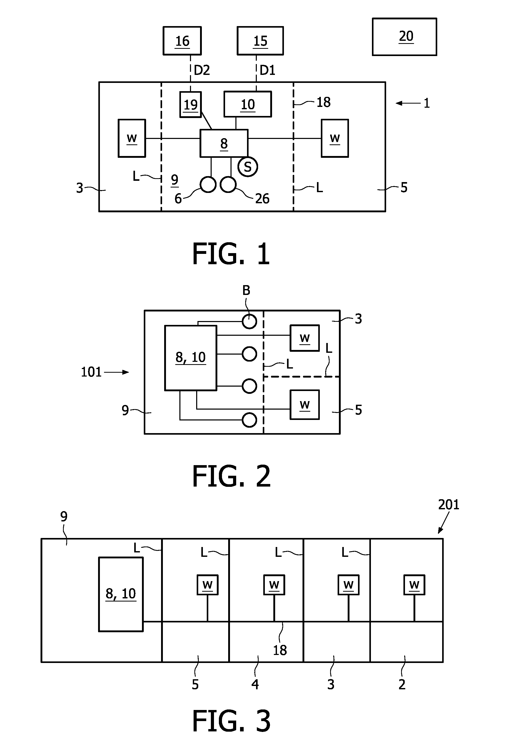
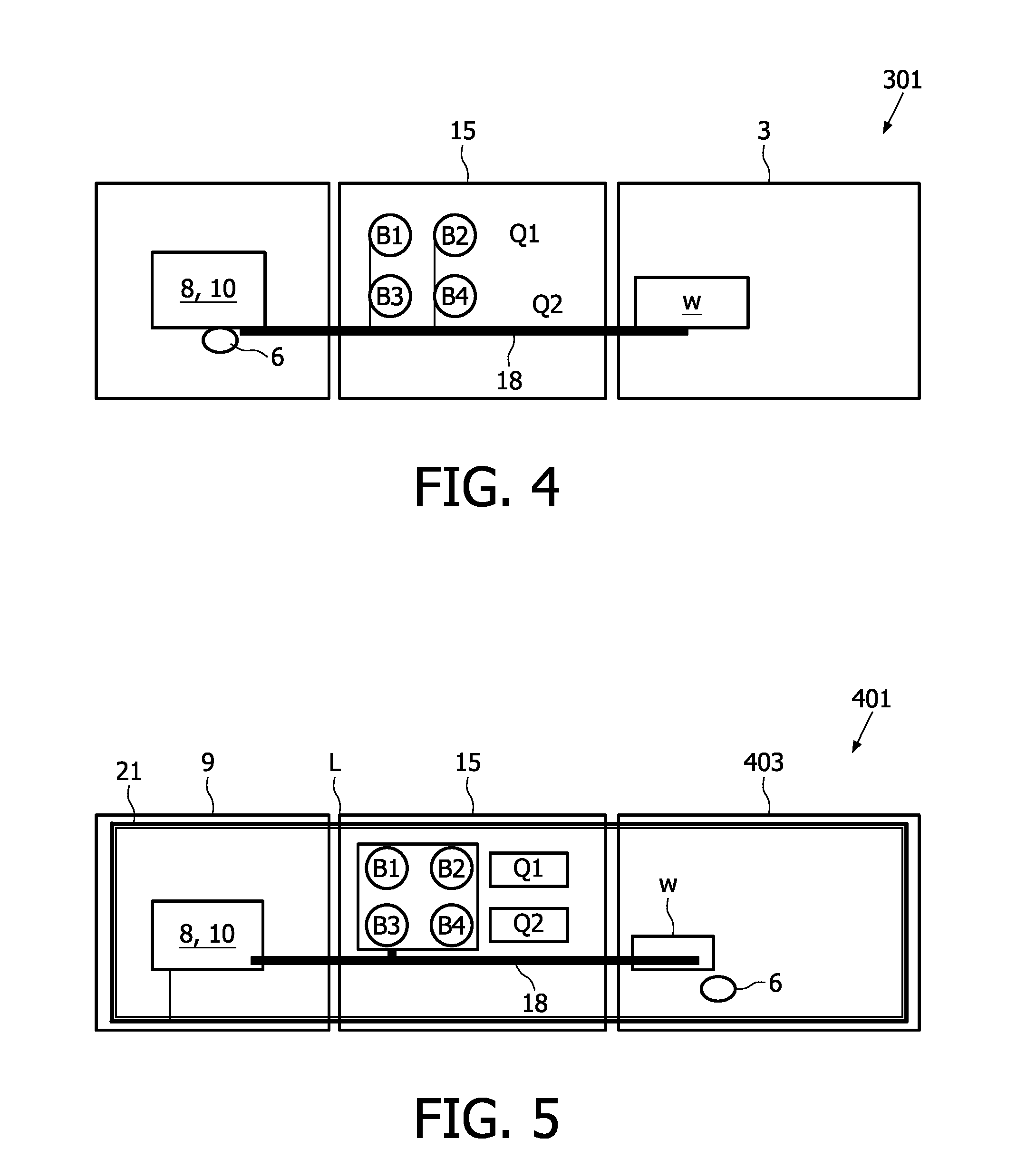
[0059]For example, in the embodiment 301 of FIG. 4, the second carrier part 9 can be provided with a user interaction means 6, for example a test ready indicator. Thus, detaching the first carrier part 3 results in a minimal loss of functionality for the device 301. As the first carrier part 3 is disposed of (it is potentially contaminated), the embodiment of FIG. 4 provides a design where functionality is placed on the recording part when possible. Specifically, any user interaction means, like the test-ready indicator 6 (or the multiple-choice buttons), are placed on the second carrier part 9. In this way, these user interaction means can be used to continue an interaction with the user, even after the carrier part 3 has been detached. For example, the second carrier part 9 needs to be returned to a central processing facility, and the user can be reminded of this aspect by causing the test-ready indicator 6 to blink at intervals, thus focusing attention of the user on the device ...

embodiment 401

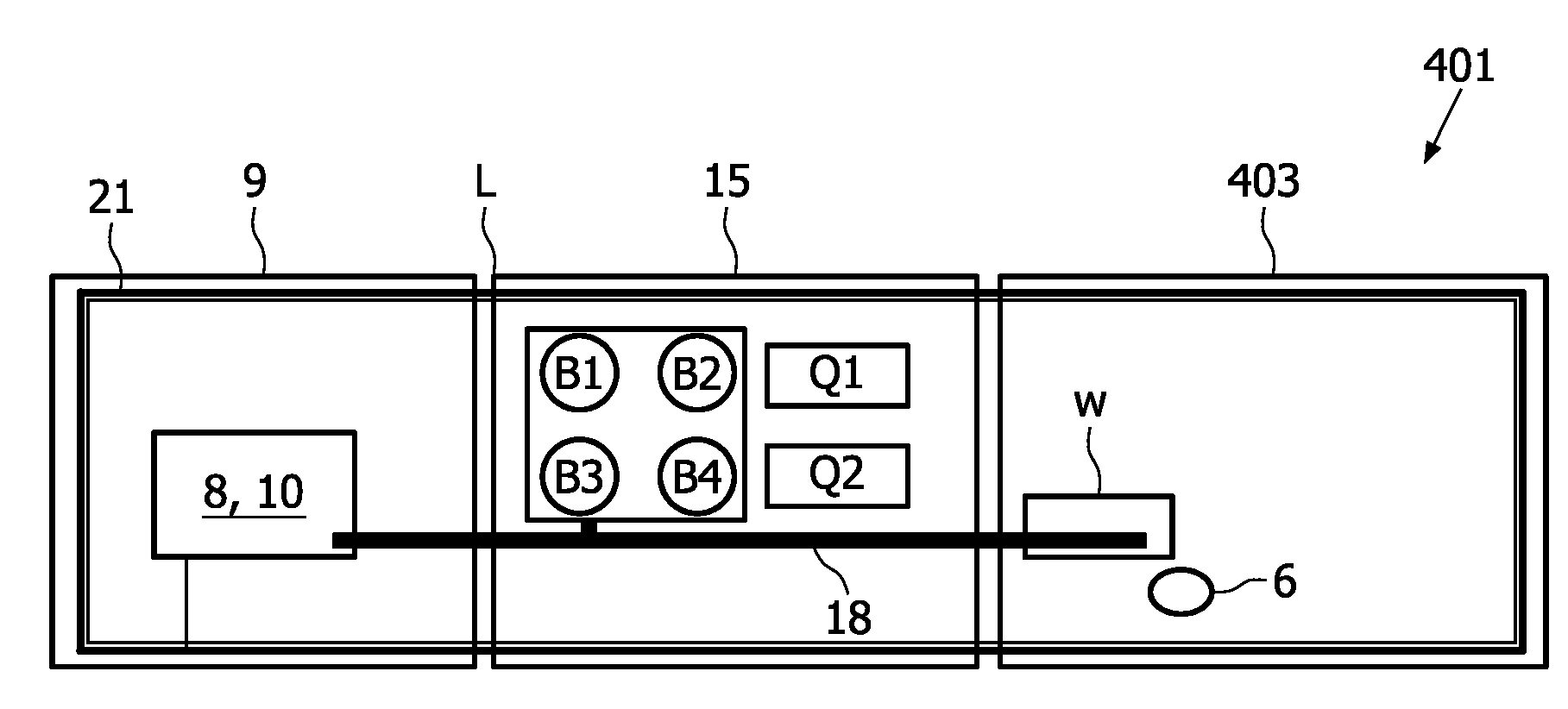
[0060]The embodiment 401 of FIG. 5 differs from the FIG. 4 embodiment in that the test ready indicator 6 is provided on the first carrier part 403. In FIG. 5, an embodiment of a tear off detection mechanism is shown, the mechanism comprising a loop 21 extending along the outer rim of the assessment device 401, for example an electric wire, which is coupled to the controller 8. As an example, the loop 21 can provide a self-test mechanism, which is to be used by the controller 8 in order to be able to determine whether the device 401 is still intact for assaying a sample. For example, if the carrier of the device 401 is constructed from a paper-like material, rips in the outer rim can be common, and can be detected via the loop 21.

[0061]Also, in an embodiment, the assay device 1, for example any of the above-described devices, can be configured to automatically switch from a low power consumption state to a high power consumption state at the start of an assay of a sample, and is pref...


PUM

PropertyMeasurementUnit
Timeaaaaaaaaaa
Fractionaaaaaaaaaa
Fractionaaaaaaaaaa

Abstract

Disposable assay device, comprising a carrier having a first carrier part (3) with a respective sample-receiving area (w) for receiving a sample to be tested, and having at least a second carrier part (9), the assay device being configured for transmitting assay data or information to a remote receiving system (20), and the device comprising at least two first carrier parts, said first carrier parts (3, 5) being independently removable from the second carrier part (9).

Description

FIELD OF THE INVENTION[0001]The invention relates to a disposable assay device, comprising a carrier having a first carrier part with a respective sample-receiving area for receiving a sample to be tested, and having at least a second carrier part, the assay device being configured for transmitting assay data or information to a remote receiving system.BACKGROUND OF THE INVENTION[0002]International patent application WO 95 / 33996 of Zwanziger et al. discloses a home test kit for use in testing for a disease or a physiological condition, with telephone verification oftest results. The known home test kit facilitates the delivery of any necessary counseling as a result of the outcome of a test. During use, an individual can obtain a sample of physiological fluid from him or herself. The sample can be introduced into an assay device to produce a coded pattern indicative of the presence or absence of the disease. The individual can transmit the coded pattern to a remote location for inte...

Claims


Application Information

Patent Timeline
IPC IPC(8): C12M1/34G06F15/00
CPCB01L3/502715B01L2200/027B01L2200/028B01L2300/0816B01L2200/10B01L2300/024B01L2200/04B01L3/00G01N30/04G01N33/48
Inventor BODLAENDER, MAARTEN PETERSTUT, WILHELMUS JOHANNES JOSEPH
Owner KONINKLIJKE PHILIPS ELECTRONICS NV
Learn More