
Plastic Embossed Carrier Tape Apparatus and Process

a technology of embossed carrier tape and manufacturing apparatus, which is applied in the direction of packaging goods, closure stoppers, caps, etc., can solve the problems of inefficiency, increased transportation costs, and increased complexity of modern semiconductors,

Active Publication Date: 2009-05-28
ADAPTSYS
View PDF37 Cites 10 Cited by
  • Summary
  • Abstract
  • Description
  • Claims
  • Application Information

AI Technical Summary

Benefits of technology

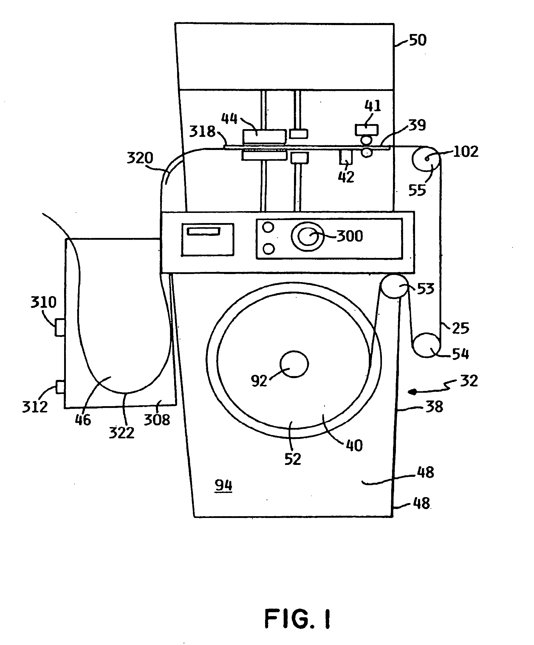
[0012]The drive assembly of the carrier tape embossing apparatus may include a drive roller and an opposing friction roller positioned so as to frictionally engage the strip therebetween, and the drive roller may be driven by a precision servo motor so that the strip is accurately and precisely positioned for the embossing process. The friction roller may be selectively positionable in at least a first position wherein the friction roller is engaged with the strip and a second position wherein the friction roller is spaced apart from the strip. The strip of plastic material may have a series of uniformly spaced sprocket holes, and the molding assembly may have a plurality of pilot pins selectively engageable with the sprocket holes. When the pilot pins are engaged with the sprocket holes during embossing, the drive mechanism may be disengaged from the strip so as to eliminate any run-out or accumulative positioning error resulting from the drive mechanism.
[0014]A punching assembly may be positioned adjacent the guide structure. The punching assembly may have at least one punch pin arranged to be selectively contactable with the pocket so as to punch a hole therein. The punch pin has a shaft with a head portion defined at a distal end thereof. The head has a first cross-sectional dimension, and the shaft has a portion with a smaller cross sectional dimension adjacent the head portion to enable the tape material to shrink slightly after the hole is punched without causing puckering or distortion in the pocket bottom.
[0015]The apparatus may further include an indexing assembly for accurately positioning the strip in the guide structure. The indexing assembly may have a ball detent mechanism with a ball portion positioned and adapted to selectively engage and register the sprocket holes in the tape.

Problems solved by technology

Modern semiconductors have become extremely complex and are highly susceptible to damage from external influences, such as contaminants, mechanical shock, electrostatic discharges and physical contact.
Previously, inefficiencies have been associated with the use of embossed carrier tape that have tended to reduce its use.
In addition to inefficiency resulting from the extra transport step itself, the rolls of carrier tape with formed pockets are much bulkier than flat rolls of carrier tape stock, leading to further transport inefficiency.
Also, the formed pockets are subject to crushing and other damage in handling.
Previous embossed carrier tape manufacturing processes have proven difficult to integrate with component filling and sealing processes.
Consequently, it is difficult to stop and start the tape manufacturing process as may be needed to accommodate a differing input rate for a pocket filling apparatus, without causing heat damage to a section of the tape or introducing an unacceptable delay while the heater is shut down and restarted.
A damaged section of tape in a roll is unacceptable and results in rejection of the entire roll.

Method used


Image

  • Plastic Embossed Carrier Tape Apparatus and Process
  • Plastic Embossed Carrier Tape Apparatus and Process
  • Plastic Embossed Carrier Tape Apparatus and Process

Examples


Embodiment Construction

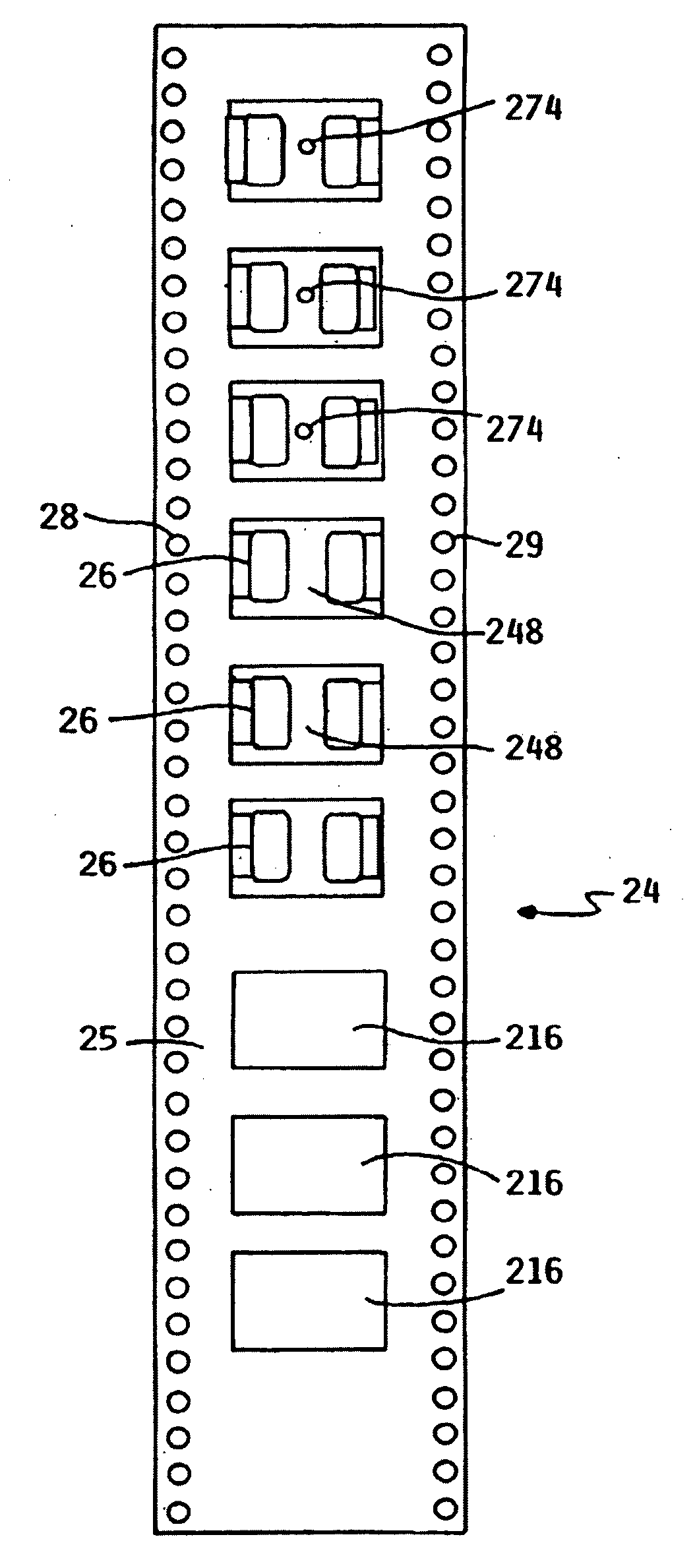
[0056]An exemplary carrier tape 24, as depicted in FIG. 3, includes a continuous strip of plastic material 25 with a series of uniformly spaced pockets 26 arranged linearly thereon. Typically, the carrier tape 24 has sprocket holes 28, 29, arranged in a uniformly spaced series along the lateral margins, thereof for moving the tape to processing equipment with sprockets. It will be readily appreciated that sprocket holes 28, 29, may be pre-punched in the carrier tape, or a punching apparatus may be added as a part of the apparatus described hereinbelow. Carrier tape 24 may be formed from a wide variety of suitable thermoplastic materials including polystyrene, polycarbonate, PETG, PET, and PVC. Any of these materials may be filled with suitable conductive material such as carbon fiber for static dissipation.

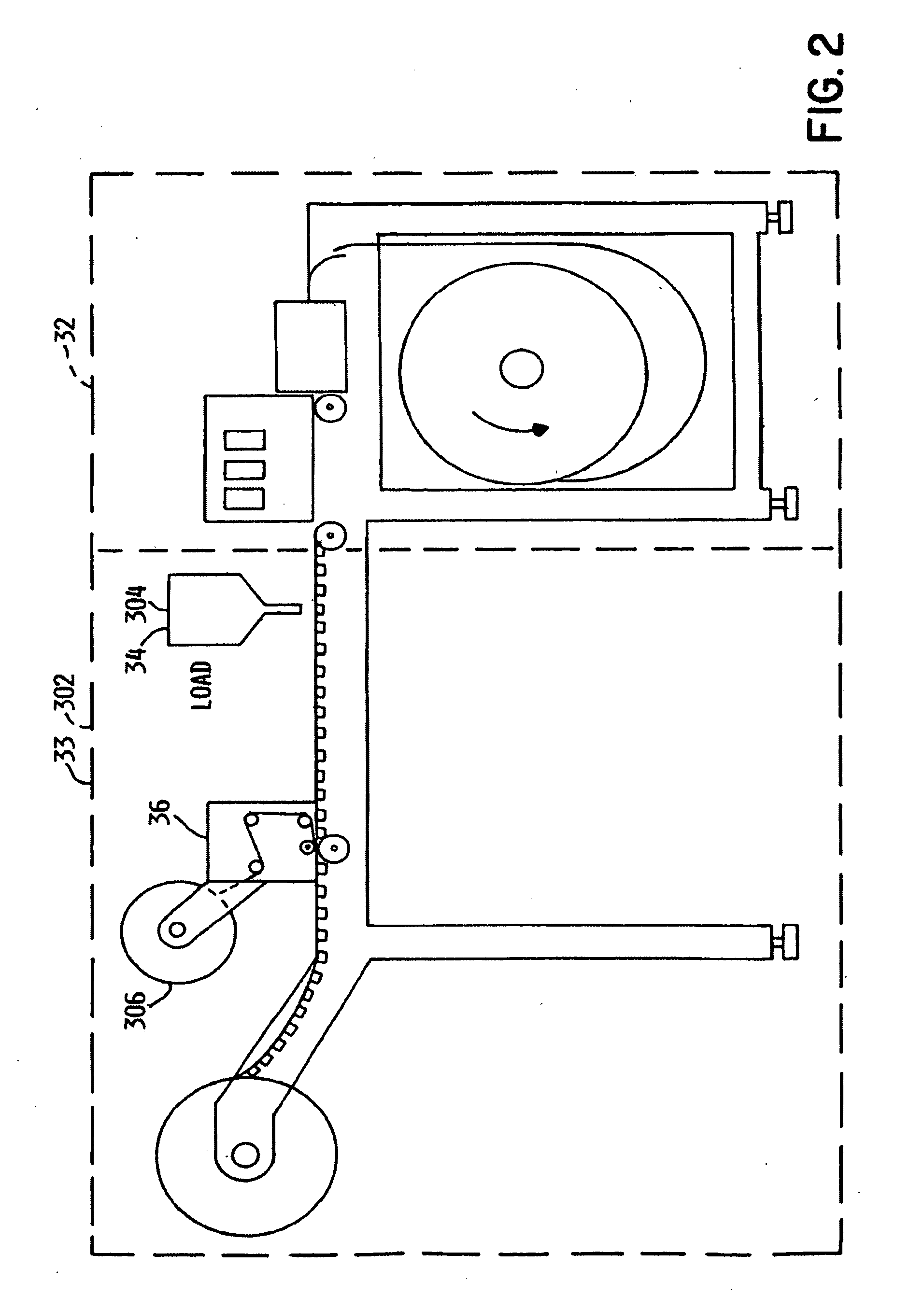
[0057]Integrated apparatus 30 generally includes carrier tape forming apparatus 32, and other processing equipment 33, such as filling apparatus 34 and sealing apparatus 36.

[0058]...


PUM

PropertyMeasurementUnit
temperatureaaaaaaaaaa
heataaaaaaaaaa

Abstract

An embossed carrier tape manufacturing apparatus includes features for integrating with other processing equipment so that other processes such as forming, filling, and sealing the tape can be performed sequentially in one integrated process. The apparatus includes retractable contact spot heaters for heating the tape prior to embossing, along with a unique heat shield arrangement that is interposable between the heaters and the tape so that the process may be paused. Also, a synchronizing apparatus is integrated so that the carrier tape embossing process may be automatically paused for adjusting to the input rate of other carrier tape processing apparatus.

Description

CLAIM TO PRIORITY[0001]The application claims priority under 35 U.S.C. § 120 to the U.S. patent application Ser. No. 10 / 815,475 filed on Apr. 1, 2004, which claims prior under 35 U.S.C. § 119(e) to the U.S. Provisional Patent application 60 / 549,335 filed on Apr. 1, 2003, the entire contents of which are incorporated herein by this referenceFIELD OF THE INVENTION[0002]The present invention relates to embossed carrier tape manufacturing apparatus and processes, and specifically to apparatus and processes for manufacturing, filling, and sealing embossed carrier tapes with electronic components.BACKGROUND OF THE INVENTION[0003]Modern semiconductors have become extremely complex and are highly susceptible to damage from external influences, such as contaminants, mechanical shock, electrostatic discharges and physical contact. Accordingly, various types of carriers have been developed to protect the delicate semi-conductors as they are transported between the many process steps needed for...

Claims


Application Information

Patent Timeline
Patent Type & Authority Applications(United States)
IPC IPC(8): B65B47/00
CPCH05K13/0084B65B47/02
Inventor GREGERSON, BARRY L.SPITZER, JAMES E.
Owner ADAPTSYS
Learn More