Particulate matter trap filter regeneration temperature control for internal combustion engine

a technology of internal combustion engine and regeneration temperature control, which is applied in the direction of electric control, machines/engines, mechanical equipment, etc., can solve the problems of difficult filter regeneration and adversely affect the fuel consumption of the engin

Inactive Publication Date: 2009-05-28
NISSAN MOTOR CO LTD
View PDF3 Cites 22 Cited by
  • Summary
  • Abstract
  • Description
  • Claims
  • Application Information

AI Technical Summary

Benefits of technology

[0005]Since a diesel engine operates by burning a fuel with excess air, the exhaust gas temperature tends to be lower than that of a spark ignition internal combustion engine, which operates by burning a fuel with a stoichiometric amount of air in most cases. On the other hand, it is necessary to raise the temperature of the particulate matter trap filter to a temperature at which particulate matter burns in order to burn the particulate matter deposited on the filter. The catalyst is disposed on the upstream side of the filter so as to generate oxidation heat by oxidizing unburnt fuel and carbon monoxide.

Problems solved by technology

When there is a change in the fuel injection characteristics of a fuel injector due to temporal degradation thereof, or when an error occurs during crank angle detection due to temporal degradation of a crank angle sensor, an actual post-injection fuel injection timing may deviate from an optimum post-injection fuel injection timing or an actual post-injection fuel injection amount may deviate from an optimum fuel injection amount.
Temporal degradation of the fuel injector or the crank angle sensor may make filter regeneration difficult or adversely affect the fuel consumption of the engine due to an excessive post-injection fuel injection amount.

Method used


Image

  • Particulate matter trap filter regeneration temperature control for internal combustion engine
  • Particulate matter trap filter regeneration temperature control for internal combustion engine
  • Particulate matter trap filter regeneration temperature control for internal combustion engine

Examples


Embodiment Construction

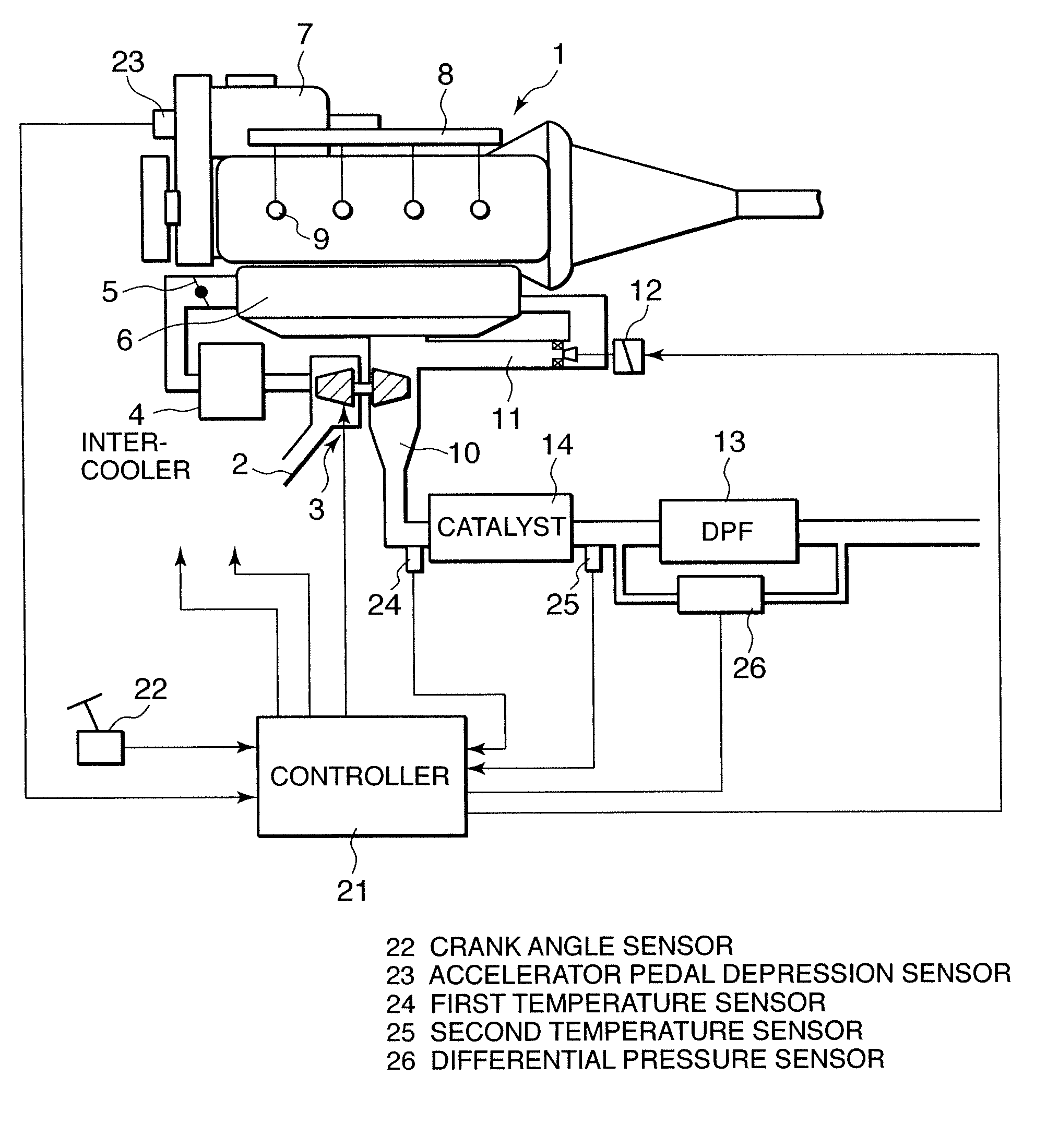
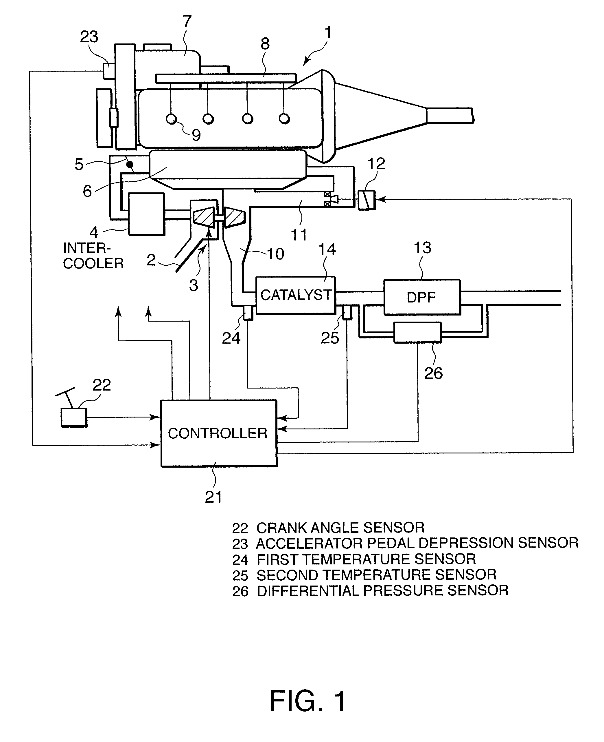
[0019]Referring to FIG. 1 of the drawings, a multi-cylinder diesel engine 1 for a vehicle comprises an intake passage 2 in which a compressor of a variable nozzle turbocharger 3, an inter-cooler 4, and an intake throttle 5 are installed. Intake air of the diesel engine 1 is turbocharged by the compressor of the turbocharger 3, cooled by the inter-cooler 4, and, after being subjected to flow rate regulation by the intake throttle 5, supplied to a combustion chamber formed in each cylinder of the diesel engine 1 via an intake collector 6.

[0020]The diesel engine 1 comprises a common-rail type fuel injection device. The common-rail type fuel injection device comprises a high-pressure fuel pump 7, a common-rail 8, and a fuel injector 9 disposed in each cylinder. The high-pressure fuel pump 7 pressurizes fuel and supplies it to the common-rail 8, and the fuel injector 9 injects the fuel stored in the common-rail 8 directly into the combustion chamber in each cylinder.

[0021]An air-fuel mix...


PUM


Abstract

An internal combustion engine (1) comprises a fuel injector (9), a filter (13) which traps particulate matter in exhaust gas, and a catalyst (14) which oxidizes unburnt fuel or carbon monoxide in the exhaust gas on the upstream side of the filter (13). When regeneration of the filter (13) is required, a controller (21) determines a post-injection fuel injection timing and a post-injection fuel injection amount of the fuel injector (9) on the basis of an upstream exhaust gas temperature (Texh) and a catalyst temperature (Tcat) (S16, S17, S19, S20, S22, S23, S25, S26, S28), thereby optimizing the regeneration temperature condition of the filter (13).

Description

FIELD OF THE INVENTION[0001]This invention relates to regeneration temperature control of a particulate matter trap filter that traps particulate matter in the exhaust gas of a diesel engine.BACKGROUND OF THE INVENTION[0002]JP2003-336520A, published by the Japan Patent Office in 2003, discloses a regeneration method for a particulate matter trap filter that traps particulate matter discharged from a diesel engine.[0003]The prior art increases unburnt fuel, which is mainly constituted by hydrocarbon (HC), and carbon monoxide (CO) in the exhaust gas when filter regeneration is required, by causing fuel injectors to perform a post-injection fuel injection in an expansion stroke or an exhaust stroke after a main injection. An oxidation catalyst or a three-way catalyst is installed in an exhaust passage of the diesel engine on the upstream side of the particulate matter trap filter so as to promote oxidation of the unburnt fuel and carbon monoxide.[0004]Oxidation heat that is generated a...

Claims


Application Information

Patent Timeline
Patent Type & Authority Applications(United States)
IPC IPC(8): F01N3/025
CPCY02T10/22F02D41/029Y02T10/12
Inventor NISHIZAWA, TORUKANEKO, HIROAKIONODERA, HITOSHI
Owner NISSAN MOTOR CO LTD
Why Eureka
Try Eureka