Working Vehicle

a technology for working vehicles and vehicles, applied in vehicle components, propulsion parts, superstructure subunits, etc., can solve the problems of time and effort required to attach the cover, the cover is likely to be incorrectly positioned, etc., to achieve the effect of preventing the increase of the temperature of the air in the engine room, and reducing the exhaust gas exhaust temperatur

Active Publication Date: 2014-09-11
KUBOTA LTD
View PDF13 Cites 21 Cited by
  • Summary
  • Abstract
  • Description
  • Claims
  • Application Information

AI Technical Summary

Benefits of technology

[0038]With this feature configuration, the exhaust path allows exhaust gas cleaned by the exhaust cleaning device to flow to the outside, so that the exhaust gas from the exhaust cleaning device has higher temperature.
[0039]However, as described above, the first outside air introduction portion and the second outside air introduction portion can be used to effectively reduce the exhaust temperature of the exhaust gas. In addition, the bonnet has an opening at a portion corresponding to an upper portion of the exhaust cleaning device, and air in the engine room is emitted through the opening to the outside, whereby the temperature of the air in the engine room can be prevented from increasing. Therefore, the air in the engine room that is introduced at the first outside air introduction portion can be caused to have lower temperature, thereby contributing to a reduction in the exhaust temperature.

Problems solved by technology

For this reason, when the cover is swung so that the horizontal plates are engaged with the engagement / disengagement mechanism, the cover is likely to be incorrectly positioned, so that the position of the cover needs to be adjusted.
Therefore, it takes time and effort to attach the cover.

Method used


Image

  • Working Vehicle
  • Working Vehicle
  • Working Vehicle

Examples


first embodiment

Variations of First Embodiment

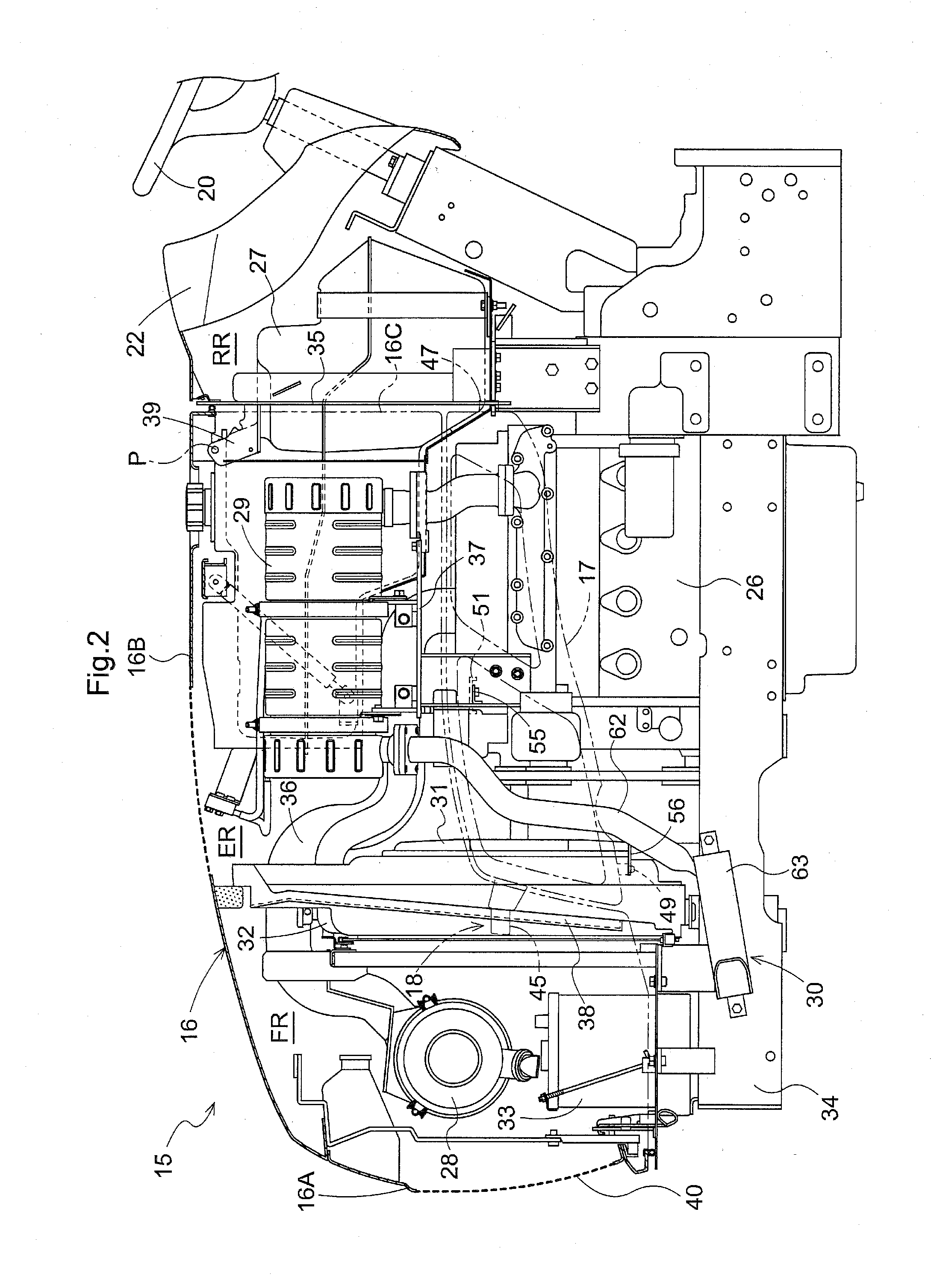
[0104](1) In the above embodiment, the first protrusion portion 45 is longer than the second protrusion portion 47. Conversely, the second protrusion portion 47 may be longer than the first protrusion portion 45.

[0105](2) In the above embodiment, the first protrusion portion 45 is exemplified as a first male engagement portion, the second protrusion portion 47 is exemplified as a second male engagement portion, the lower protrusion portion 49 is exemplified as a third male engagement portion, the first insertion hole 46 is exemplified as a first female engagement portion, the second insertion hole 48 is exemplified as a second female engagement portion, and the positioning hole 50 is exemplified as a third female engagement portion. These protruding portions are engaged with these insertion holes. The present invention is not limited to this. Alternatively, for example, the first, second, and third male engagement portions may be a hook-like member, and...

second embodiment

[0109]Another example of the present invention will be described with reference to the drawings.

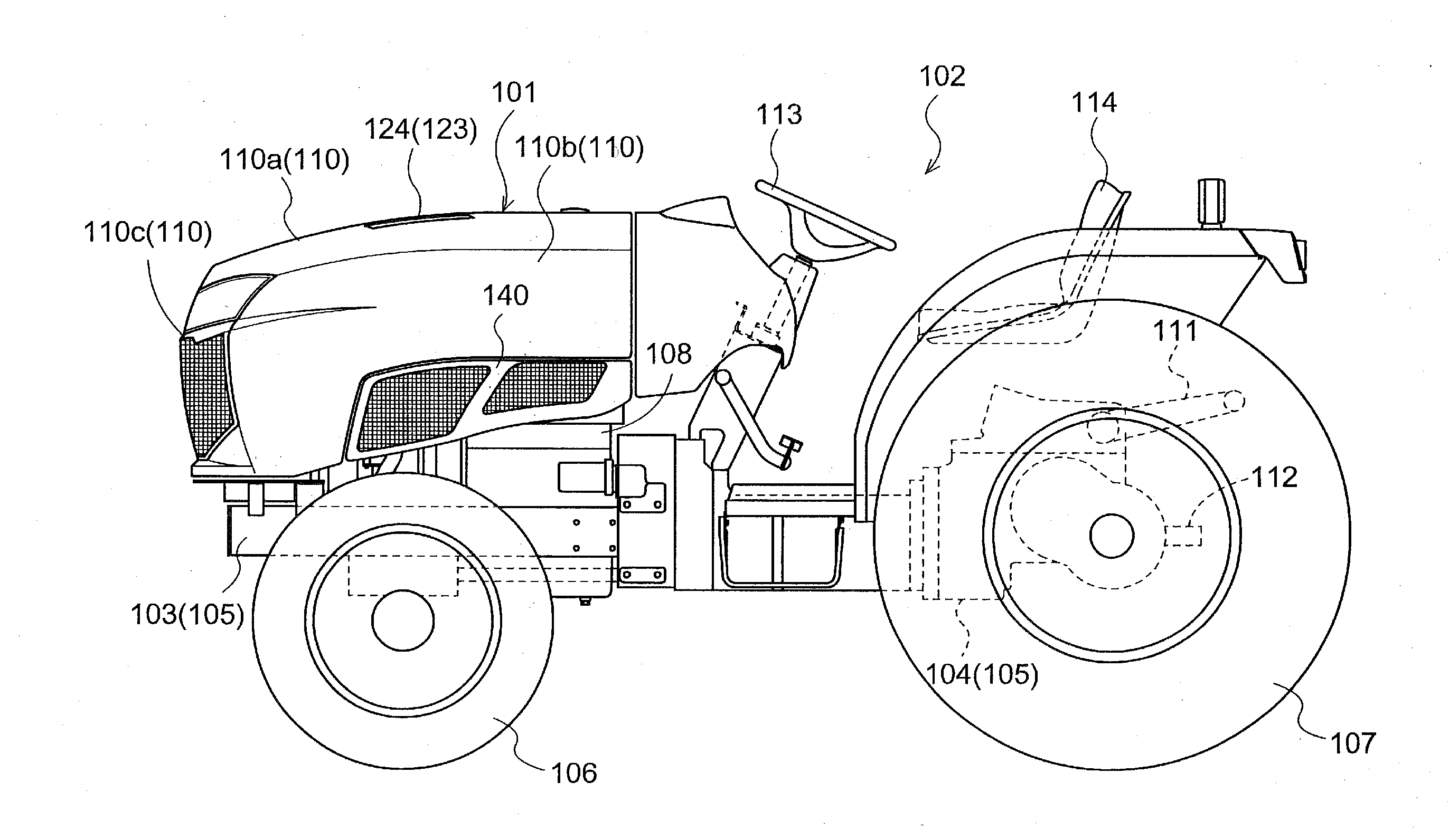
[0110]FIG. 14 shows an entire side surface of a tractor that is an example working vehicle according to the present invention.

[0111]This tractor includes a drive unit 101 that is provided in a front portion of the vehicle body, and a maneuvering unit 102 that is provided in a middle portion of the vehicle body behind the drive unit 101. An engine mounting frame 103, a clutch housing (not shown), and a mission case 104 are integrally linked together to form a vehicle body frame 105. The drive unit 101 is mounted on the engine mounting frame 103. The vehicle body frame 105 is supported by a pair of left and right front wheels 106 and a pair of left and right rear wheels 107.

[0112]As shown in FIGS. 14 and 15, in the drive unit 101, an engine 108 that is a diesel engine is provided on the engine mounting frame 103 and supported by an anti-vibration material (not shown) that reduces or prevent...


PUM


Abstract

A working vehicle includes a traveling machine assembly, a drive unit, a bonnet configured to cover the drive unit, and a cover provided below the bonnet and configured to be removably attached to the traveling machine assembly, including a main body portion extending in a longitudinal direction of the traveling machine assembly, a first male engagement portion provided at a front end portion of the main body portion, a second male engagement portion provided at a rear end portion of the main body portion, and a third male engagement portion provided at a lower end portion of the main body portion.

Description

CROSS-REFERENCE TO RELATED APPLICATIONS[0001]This application claims priority to Japanese Patent Application Nos. 2013-045352 and 2013-045354, both filed Mar. 7, 2013, the disclosures of which are hereby incorporated in their entirety by reference.BACKGROUND OF THE INVENTION[0002]1. Field of the Invention[0003]The present invention relates to working vehicles.[0004]2. Description of the Related Art[0005]A working vehicle has been proposed that includes a cover that is located below a bonnet covering a drive unit and is removably attached to a traveling machine assembly. An example cover attachment structure in such a working vehicle is described in, for example, JP 2004-122877A (particularly, FIG. 4). In the cover attachment structure of JP 2004-122877A, two attachment holes are provided in a lower end portion of the cover, two (upper and lower) horizontal plates are provided on an inner surface of the cover, engaging / retaining pieces are provided in a lower portion of the traveling...

Claims


Application Information

Patent Timeline
Patent Type & Authority Applications(United States)
IPC IPC(8): B62D25/12B60K13/04B62D25/08
CPCB62D25/12B60K13/04B62D25/082B62D25/10B60Y2200/221B60K13/06
Inventor AOYAMA, KENICHIKASHIYAMA, SHINSUKEMATSUDA, SHINICHIROSAWAI, MEGUMISUGANO, KAZUNOBU
Owner KUBOTA LTD
Why Eureka
Try Eureka