Climate control system and method for a greenhouse

a greenhouse and climate control technology, applied in the field of greenhouses with a controlled climate, can solve the problems of insufficient evaporative cooling effect, difficult to maintain an elevated cosub>2 /sub>concentration, and attenuating any benefi

Active Publication Date: 2015-10-20
TROPOS TECH LLC
View PDF8 Cites 19 Cited by
  • Summary
  • Abstract
  • Description
  • Claims
  • Application Information

AI Technical Summary

Benefits of technology

[0008]To solve one or more of the problems set forth above, in an exemplary implementation of the invention, a greenhouse system is provided that maintains (1) a positively pressurized CO2-enriched air environment with a CO2 concentration of about 1,200 ppm, (2) an air temperature of between 60 F and 75° F., (3) a relative humidity of between 50% and 70% except under extreme summer conditions, and (4) lighting between about 200 micro mols / square meter / sec and 600 micro mols / square meter / sec during lighted conditions. An exemplary system according to principles of the invention uses urea and selective catalytic reduction (SCR) to reduce pollutants in exhaust gases from combustion of natural gas. Ammonia produced by hydrolysis of urea reacts with nitrogen oxide emissions and is converted into nitrogen and water. An exemplary system according to principles of the invention uses direct heat double effect absorption chillers as a primary heat recovery device to provide both heating and cooling. Direct contact condensing heat exchangers reduce exhaust gas temperature from about a nominal 300° F. to approximately 130° F. in order to more efficiently use the heat in a greenhouse. A mixing and blending unit maintains positive control of entering outside air. Outside air is drawn through a fine particle filter to prevent insects and other airborne foreign matter from entering the mixing and blending unit and greenhouse. Using a fan and optional damper, the mixing and blending unit controls the intake of outside air to constantly maintain both the oxygen and CO2 level within an acceptable range of setpoint values.
[0009]Ductwork leads from an outlet of the mixing and blending unit to fan and coil units. The fan and coil units have outlets within the greenhouse. The fan and coil units maintain a positive pressure in the greenhouse which will continually expel air from the greenhouse out of one or more vents, such as a screened roof vent, and return ductwork, allowing for additional cooled and dehumidified air to enter the greenhouse through the fan and coil units. Concomitantly, the fan and coil units provide a negative pressure to the mixing and blending Unit to assist in drawing in the outside air, without imposing a back pressure on the generator that is providing CO2.

Problems solved by technology

Thus, in hot humid climates, the evaporative cooling effect is typically insufficient to maintain a greenhouse at a temperature favorable to plant growth.
In greenhouses with fan and pad evaporative cooling systems, it is difficult to maintain an elevated CO2 concentration, notwithstanding enrichment efforts.
This attenuates any benefit to photosynthesis while increasing production costs and compromising the outside environment.

Method used


Image

  • Climate control system and method for a greenhouse
  • Climate control system and method for a greenhouse
  • Climate control system and method for a greenhouse

Examples


Embodiment Construction

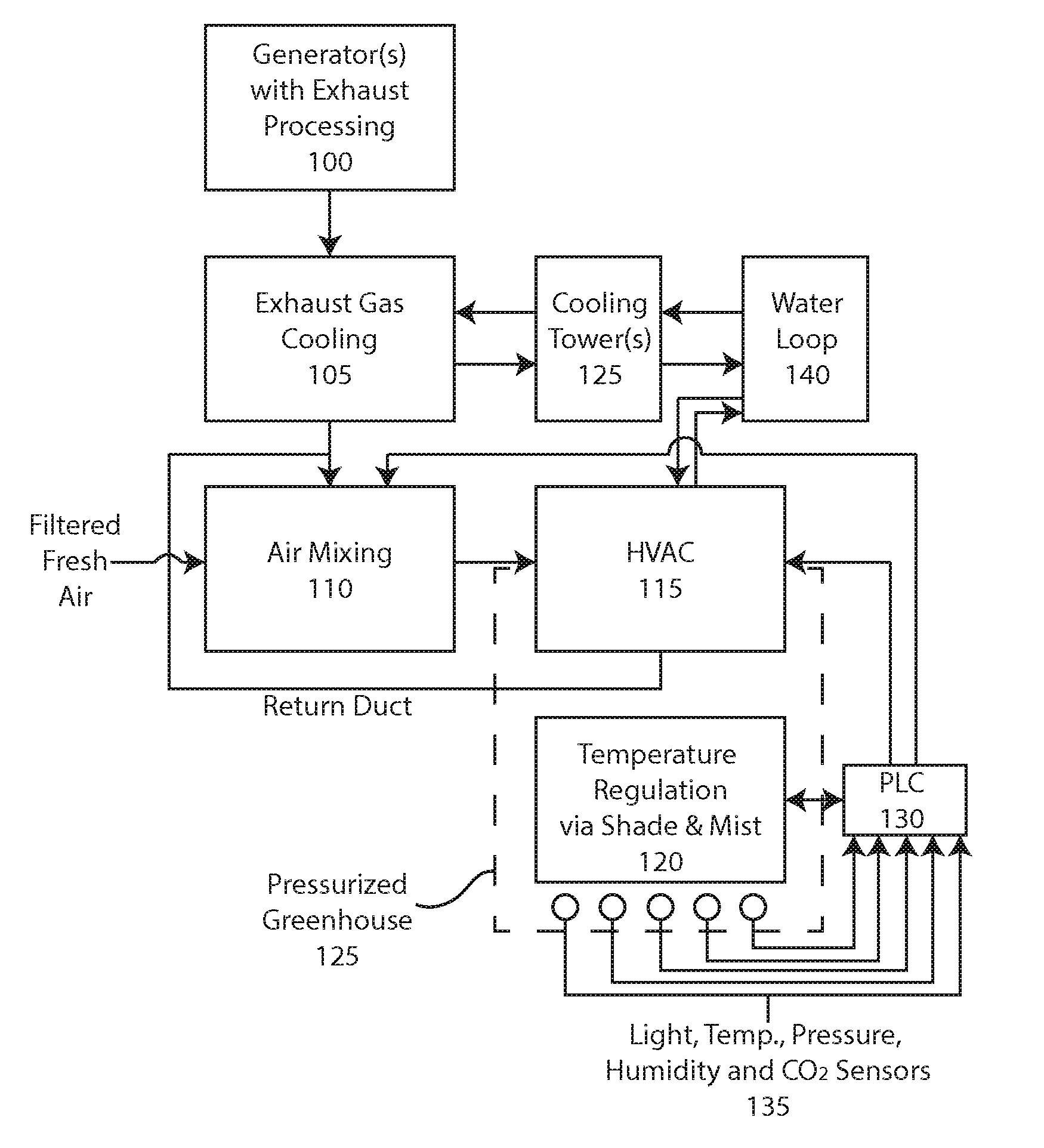
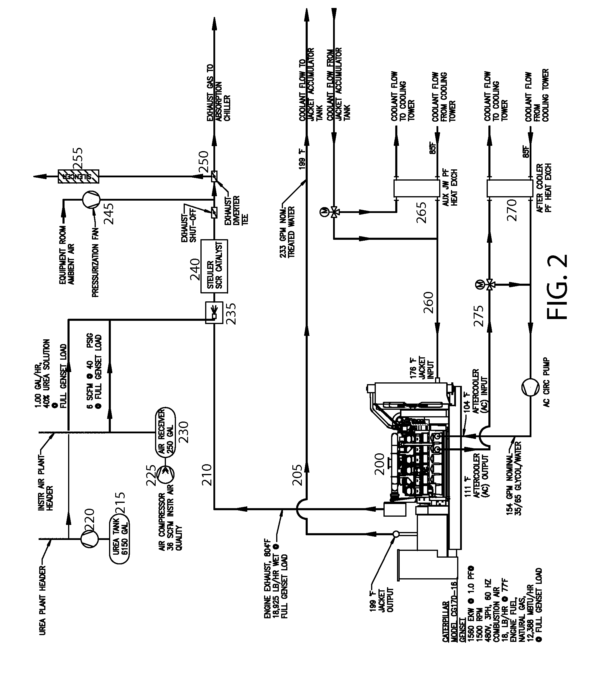
[0031]A climate control system for a greenhouse according to principles of the invention provides electricity, water, heating, cooling, dehumidification and CO2 enriched air to the interior of a greenhouse for purposes of facilitating plant growth. With reference to the high level block diagram of FIG. 1, the system is comprised of a number of operably coupled subsystems that supply the aforementioned utilities and provide the functionality. The greenhouse 125 is substantially closed, excepting screened vents, and positively pressured to prevent intrusion by contaminants, pests and ambient air, it is not suitable for fan and pad evaporative cooling which requires an open path for rapid airflow to facilitate evaporative cooling. The subsystems include one or more generator subsystems 100 which simultaneously produce electricity for lighting and / or sale to a local grid, hot water for heating, and CO2 for enhanced photosynthesis. Nox from the generator exhaust is removed by reaction wi...


PUM


Abstract

A greenhouse environment control system generates a CO2-enriched air which is supplied to a greenhouse at a controlled temperature suitable for plant growth. An absorption chiller reduces temperature of a CO2-containing stream of processed gasses from an engine. A mixing and blending unit maintains CO2 at an acceptable concentration for enhanced plant growth and human occupation. An HVAC system modulates temperature and positively pressurizes the greenhouse with the CO2-enriched air to reduce risk of contaminant intrusion. Misting further controls temperature. Retractable shades regulate light supplied to plants and solar gain.

Description

FIELD OF THE INVENTION[0001]This invention relates generally to horticulture, and, more particularly, to a greenhouse with a controlled climate, including temperature, humidity and carbon dioxide concentration.BACKGROUND[0002]Commercial greenhouses are high tech production facilities for vegetables and flowers. Heretofore, such greenhouses have been adapted for use in regions with cold winters and arid summers. In such climates, the greenhouse interior may be heated in winter months such as by using boilers, heat pumps, or heat transferred from hot engine exhaust. Such greenhouses may be cooled during hot summer months through evaporative cooling systems. One example of such a cooling system is a pad and fan, which draws dry outside air through a wet porous pad to cool the air via evaporative cooling. To work, the fan must continuously draw ambient air through the pad and exhaust the cooled air to the outside. Fogging and misting systems are also widely used to cool greenhouses in a...

Claims


Application Information

Patent Timeline
Patent Type & Authority Patents(United States)
IPC IPC(8): A01G9/18
CPCA01G9/18A01G9/246Y02A40/25
Inventor SHELOR, F. MACK
Owner TROPOS TECH LLC
Why Eureka
Try Eureka