Portable supporting frame for cutting machine

a technology of supporting frame and cutting machine, which is applied in the direction of folding cycle, transportation/perambulator with multiple axes, manufacturing tools, etc., can solve the problem of losing one of the parts, and achieve the effect of quick and easy folding

Inactive Publication Date: 2009-05-28
LEE WY PERON
View PDF8 Cites 9 Cited by
  • Summary
  • Abstract
  • Description
  • Claims
  • Application Information

AI Technical Summary

Benefits of technology

[0013]A main object of the present invention is to provide a portable supporting frame for a cutting machine, which is capable of being quickly and easily folded for carriage and storage and unfolded for supporting the cutting machine.

Problems solved by technology

Firstly, the cutting head comprises a motor and a transmission means positioned above the supporting frame, wherein the floor standing frame must support the heavy weight of the cutting head. In fact, the four-leg structure of the floor standing frame is weak structure to support the heaving weight. Therefore, the four standing legs of the floor standing frame must be made of strong material such as cast iron or steel alloy can be securely fastened to the four construction posts in order to rigidly support the heavy cutting head.
Secondly, the floor standing frame requires assembly or disassembly to use or store. The floor standing frame is detachably attached on the supporting by means of the four standing legs can be detached from the four construction posts of the supporting frame respectively. So, the user must assemble the floor standing frame when the cutting machine is needed to be used and disassemble the four standing legs from the supporting frame after using the cutting machine.
Thirdly, the floor standing frame, which is constructed by several parts, includes four standing legs and several connecting bolts. When the floor standing frame is disassembled for transportation or storage, the user must carry or store all the several parts of the floor standing frame because it is easy to loss one of the parts.
Fourthly, when the floor standing frame is assembled for use, the user must need a tool to attach the floor standing frame to the supporting frame so as to connect the standing legs to the construction posts by screwing the connecting bolts. Likewise, the user must use a tool to unscrew the connecting bolts in order to detach the standing legs from the construction posts when disassembling the floor standing frame.

Method used


Image

  • Portable supporting frame for cutting machine
  • Portable supporting frame for cutting machine
  • Portable supporting frame for cutting machine

Examples


Embodiment Construction

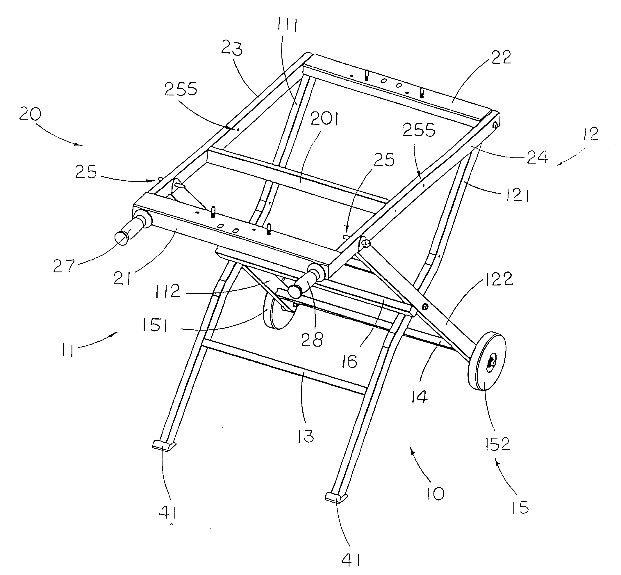
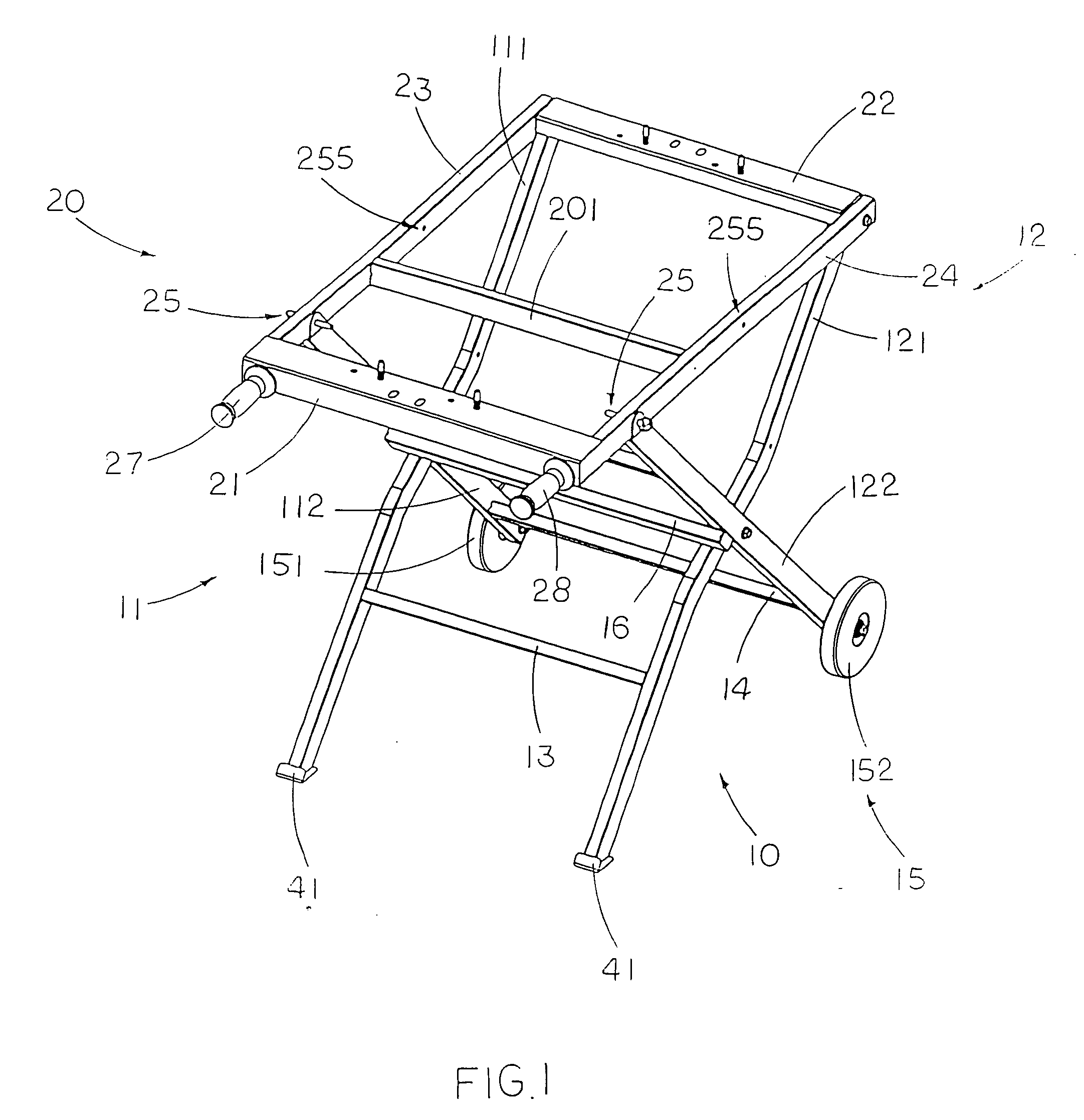
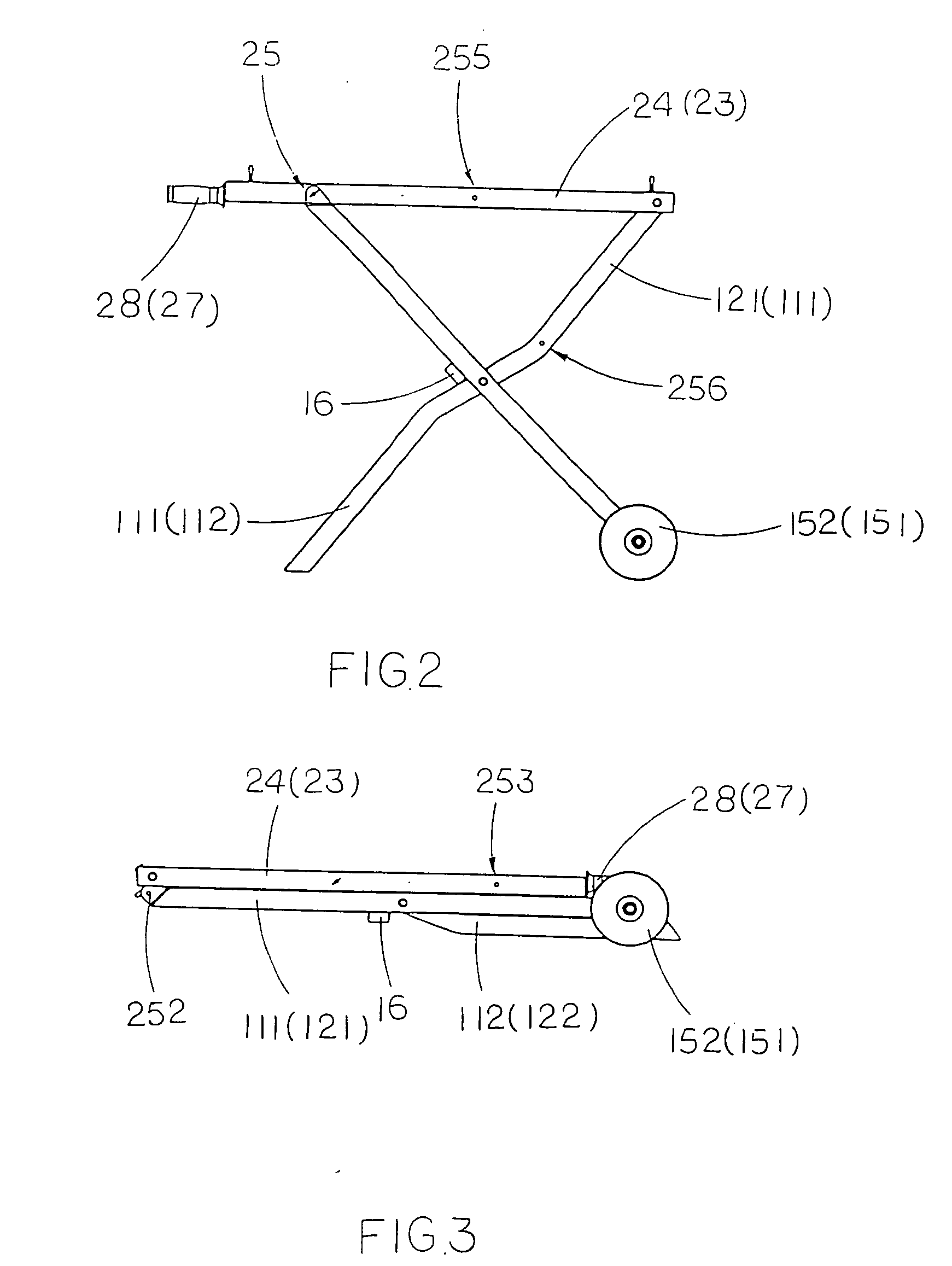
[0034]Referring to FIGS. 1, 2 and 3 of the drawings, a portable supporting frame for a cutting machine, according to a preferred embodiment of the present invention is illustrated, in which the portable supporting frame comprises a leg frame 10 and a tabletop frame 20.

[0035]The leg frame 10 comprises two opposing pairs of supporting legs 11, 12, two linking member 13, 14 and a transportation unit 15. Each of the two opposing pairs of supporting legs 11, 12 comprises a pair of first and second crossed legs 111, 112, 121, 122 pivotally and crossly connected together. The two linking member 13, 14 are a first linking member 13 for supporting the two first crossed legs 111, 121 in parallel manner and a second linking member 14 for supporting the two second crossed legs 112, 122 in parallel manner. In other words, the first linking member 13 is perpendicularly extended between the two first crossed legs 111, 121, while the second linking member 14 is perpendicularly extended between the ...


PUM

PropertyMeasurementUnit
thicknessaaaaaaaaaa
lengthaaaaaaaaaa
weightaaaaaaaaaa

Abstract

A portable supporting frame for a cutting machine includes a leg frame, a tabletop frame, and a frame locker. The leg frame includes two opposing pairs of first and second supporting legs. The tabletop frame includes two table arms pivotally connected to the first crossed legs respectively. The frame locker is used for locking the top ends of the second crossed legs to the table arms respectively to retain the portable supporting frame at a set up position. When the frame locker is released, the tabletop frame is adapted to pivotally fold at 180° to overlap on the folded leg frame at a folded position.

Description

CROSS REFERENCE OF RELATED APPLICATION [0001]This is a non-provisional application of a provisional application having an application No. 61 / 004,136 and a filing date of Nov. 23, 2007.BACKGROUND OF THE PRESENT INVENTION [0002]1. Field of Invention[0003]The present invention relates to a table frame, and more particularly to a portable supporting frame for cutting machine, which is capable of being quickly and easily folded for carriage and storage and unfolded for supporting the cutting machine.[0004]2. Description of Related Arts[0005]A conventional cutting machine is commonly used in the construction industry for shaping and cutting materials such as ceramic tile, marble, granite, and natural stone. The conventional cutting machine usually comprises a cutting table supported on a supporting frame, four construction posts positioned at four corners of the supporting frame, a cutting head overhanging the cutting table with a circular saw blade which is powered by an electric motor. ...

Claims


Application Information

Patent Timeline
Patent Type & Authority Applications(United States)
IPC IPC(8): B25H1/04
CPCB25H1/04Y10T83/95
Inventor LEE, WY PERON
Owner LEE WY PERON
Why Eureka
Try Eureka