
Method for Controlling a Communication Between Two Areas By Electrowetting, a Device Including Areas Isolatable From Each Other and Method for making Such a Device

a communication method and communication technology, applied in the direction of diaphragms, electrostatic separators, electric/magnetic elements, etc., to achieve the effect of great flexibility

Inactive Publication Date: 2009-05-28
COMMISSARIAT A LENERGIE ATOMIQUE ET AUX ENERGIES ALTERNATIVES
View PDF1 Cites 172 Cited by
  • Summary
  • Abstract
  • Description
  • Claims
  • Application Information

AI Technical Summary

Benefits of technology

[0018]An object to the present invention is also to provide great flexibil...

Problems solved by technology

However, manufacturing such valves requires provision of their location during the making of the chip and the use of a physical mask and of light insolation in order to carry out local polymerization.

Method used


Image

  • Method for Controlling a Communication Between Two Areas By Electrowetting, a Device Including Areas Isolatable From Each Other and Method for making Such a Device
  • Method for Controlling a Communication Between Two Areas By Electrowetting, a Device Including Areas Isolatable From Each Other and Method for making Such a Device
  • Method for Controlling a Communication Between Two Areas By Electrowetting, a Device Including Areas Isolatable From Each Other and Method for making Such a Device

Examples


Embodiment Construction

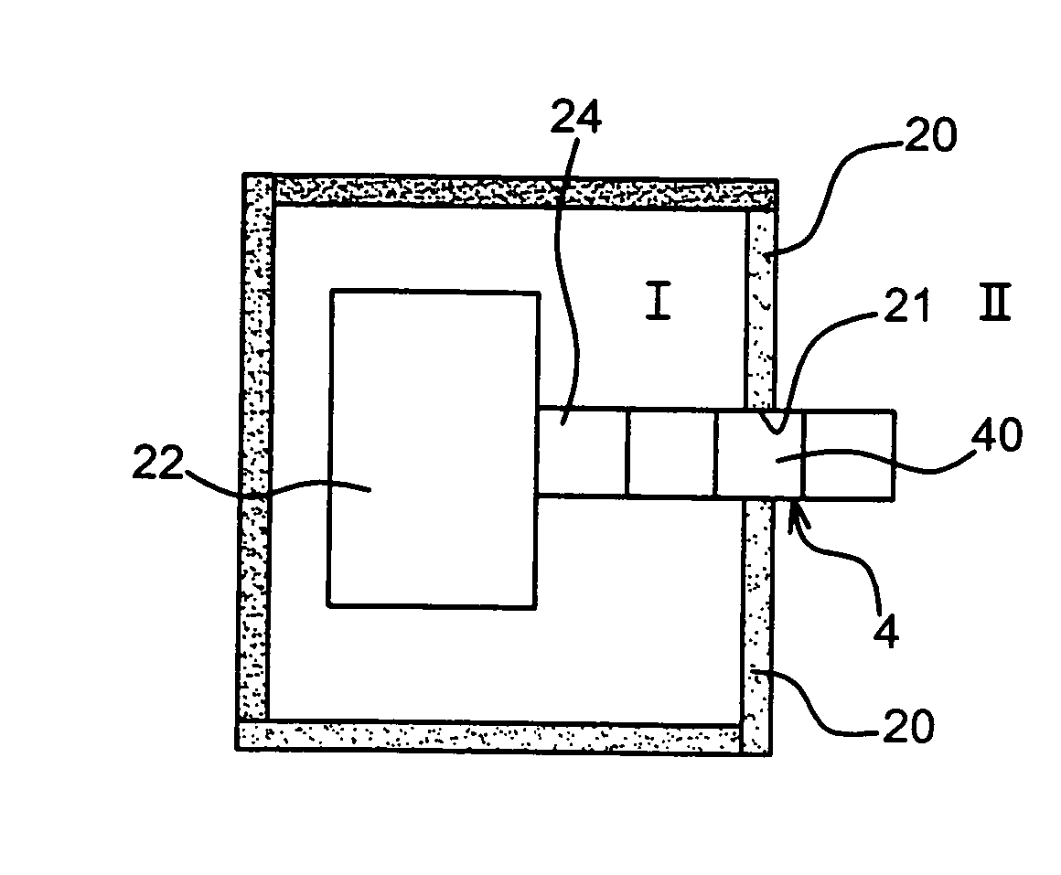
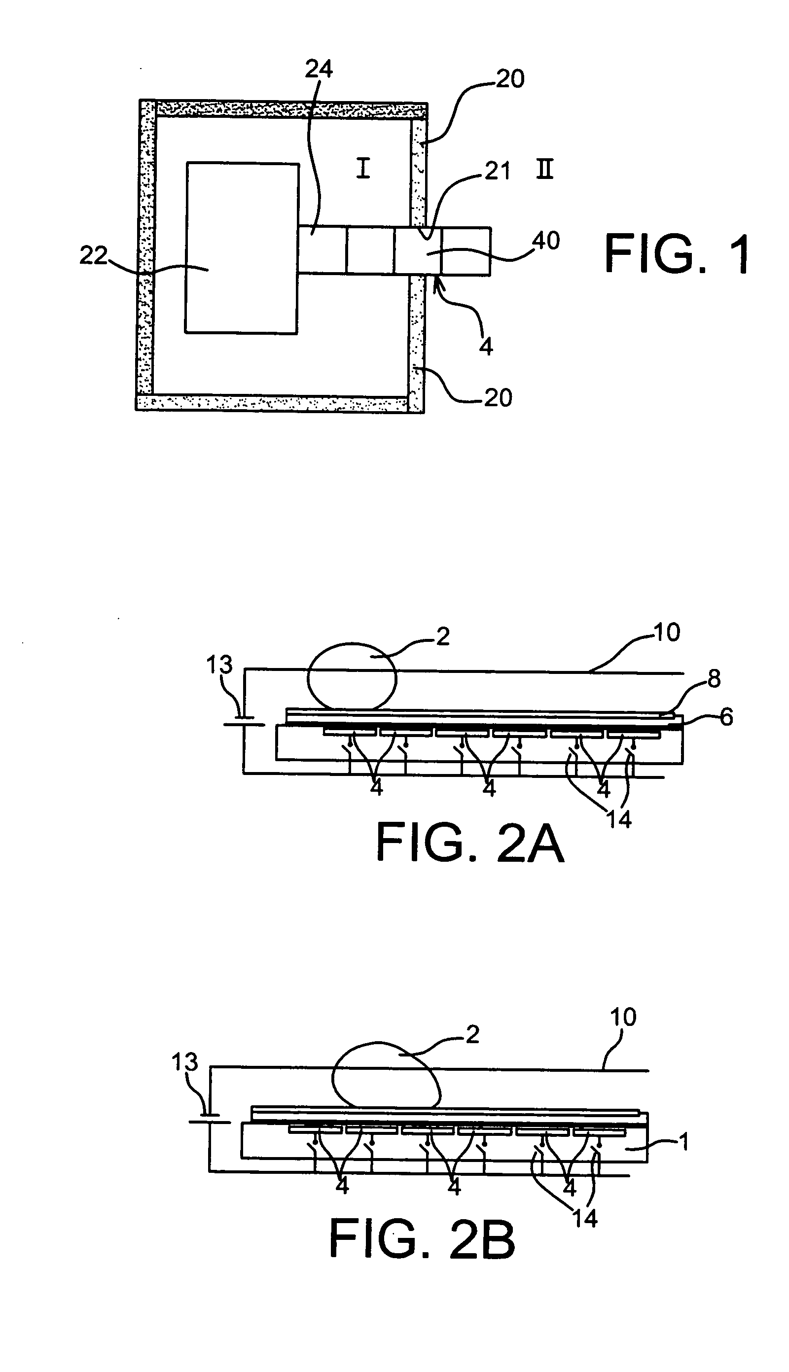
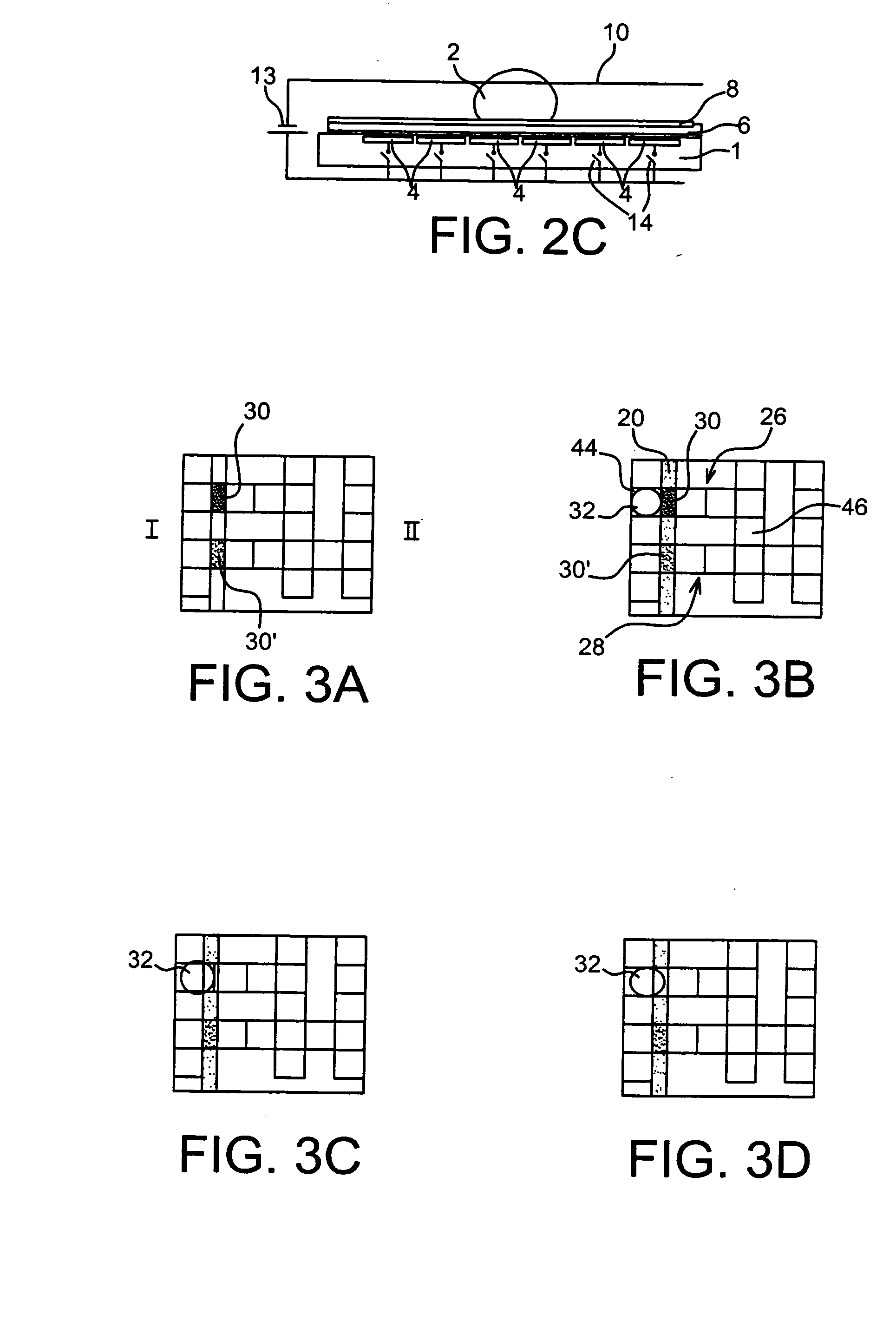
[0061]In FIG. 1, a device according to the present invention may be seen including at least one area I, one area II, separated by a partition 20, for example in resin. The partition 20 includes at least one aperture 21 providing communication between the areas I and II. These areas I, II form compartments capable of receiving products which one wishes to isolate from each other, at least for a certain time. Only two compartments are illustrated, however more than two compartments may be provided as this will be described subsequently. The communication passages will be provided according to the type of compartment.

[0062]The device according to the invention is, a microsystem for example, an analysis chip, a so-called biochip, on which reactions between small drops or small volumes of liquid are conducted. These drops of liquid are advantageously displaced by electrowetting.

[0063]The compartment I includes a reservoir electrode 22 on which the product to be isolated from the area II ...


PUM

PropertyMeasurementUnit
Temperatureaaaaaaaaaa

Abstract

Device for displacing drops of liquid by electrowetting, and a method for isolating two areas delimited by at least one wall including a step for:placing by electrowetting, in an aperture of said wall, a substance capable of reacting to at least one external stimulus in order to pass from a liquid state to a gel or solid state, forming a closure member.

Description

TECHNICAL FIELD AND PRIOR ART[0001]The present invention relates to a method for controlling a communication between two areas by electrowetting, to a device including areas isolatable from each other and capable of containing, notably, liquids, solids and / or gases and to a method for making such a device.[0002]One of the most used displacement or handling modes is based on the principle of electrowetting on a dielectric, as described in the article of M. G. Pollack, A. D. Shendorov, R. B. Fair, entitled <<Electrowetting-based actuation of droplets for integrated microfluidics>>, Lab Chip 2 (1) (2002) 96-101.[0003]The forces used for the displacement are electrostatic forces.[0004]Document FR 2 841 063 describes a device applying a catenary facing electrodes activated for the displacement.[0005]The principle of this type of displacement is the following.[0006]A drop lies on a network of electrodes, from which it is isolated by a dielectric layer and a hydrophobic layer.[...

Claims


Application Information

Patent Timeline
IPC IPC(8): B01D57/02B05D5/12
CPCF15C5/00F16K99/0001F16K2099/0084F16K99/0042F16K2099/008F16K99/0017
Inventor JARY, DOROTHEE
Owner COMMISSARIAT A LENERGIE ATOMIQUE ET AUX ENERGIES ALTERNATIVES
Learn More