Arrangement for a direct drive generator for a wind turbine and method for the assembly of the generator

a direct drive and wind turbine technology, applied in the direction of magnetic circuit rotating parts, magnetic circuit shape/form/construction, greenhouse gas reduction, etc., can solve the problems of difficult handling of stator segments and rotor segments, and achieve the effect of simplifying transportation

Active Publication Date: 2009-05-28
FLENDER GMBH
View PDF17 Cites 40 Cited by
  • Summary
  • Abstract
  • Description
  • Claims
  • Application Information

AI Technical Summary

Benefits of technology

[0033]each stator/rotor segment unit is arranged on the ring-shaped supporting elements of the stator and on the ring-shaped supporting elements of the rotor, wherein each stator segment of each stator/rotor segment unit is arranged on the ring-shaped supporting elements of the stator and each rot

Problems solved by technology

However in practice the handling of the stator segments and of the rotor segments can be difficult in particular when e.g. a stator element of a st

Method used


Image

  • Arrangement for a direct drive generator for a wind turbine and method for the assembly of the generator
  • Arrangement for a direct drive generator for a wind turbine and method for the assembly of the generator
  • Arrangement for a direct drive generator for a wind turbine and method for the assembly of the generator

Examples


Embodiment Construction

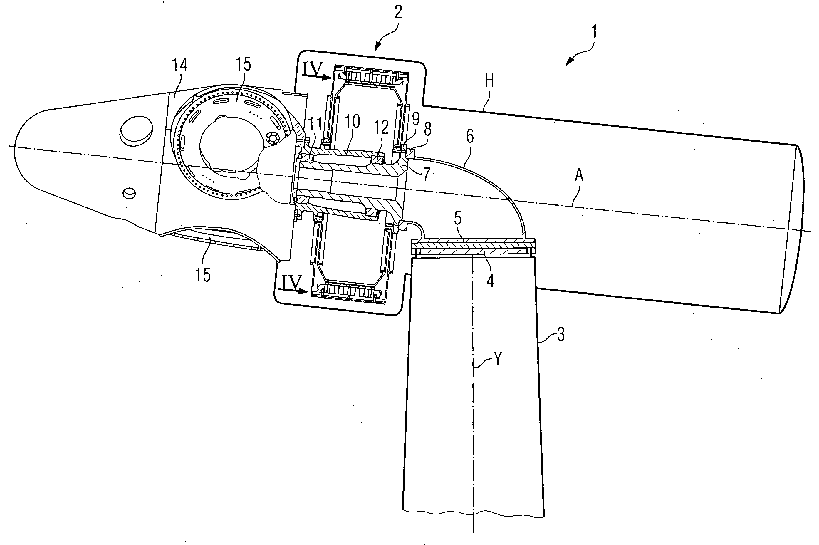
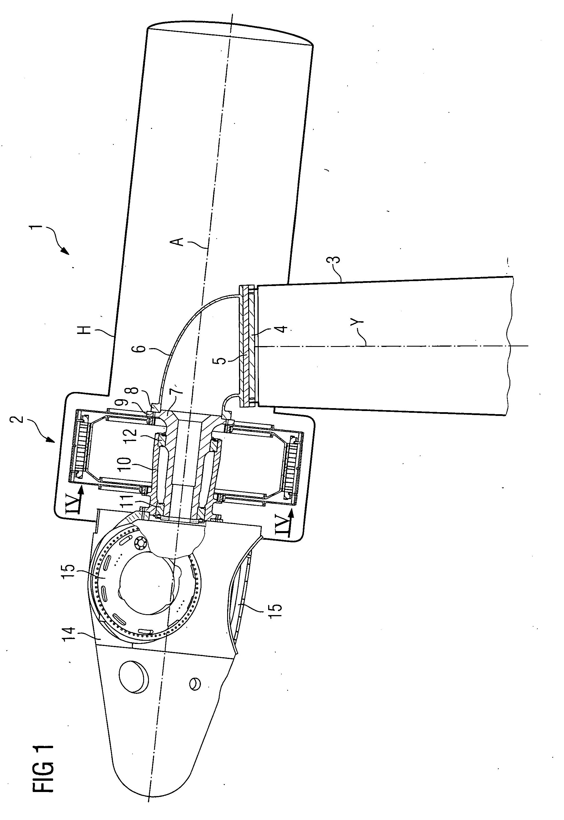
[0041]FIG. 1 shows schematically a first embodiment of an inventive wind turbine 1 comprising an inventive direct drive or directly driven generator 2 which is arranged on the upwind side of a tower 3 of the wind turbine 1.

[0042]A tower flange 4 is arranged on the top of the tower 3. A retaining arrangement is arranged on the tower flange 4 comprising in case of the present embodiment of the invention a bedplate 5, a retaining frame in form of a retaining arm 6 and a stationary or fixed hollow shaft 7. The bedplate 5 is attached to the tower flange 4. The wind turbine 1 comprises in a not explicitly shown manner a yaw system for turning the bedplate 5 of the wind turbine 1 around the centre axis Y of the tower 3 together with the other components of the wind turbine 1 which are directly or indirectly attached to the bedplate 5.

[0043]The retaining arm 6 is on its base side directly arranged on the bedplate 5. On the other side the retaining arm 6 comprises a flange 8. The stationary ...


PUM


Abstract

The invention concerns an arrangement for a direct drive generator for a wind turbine, which generator comprises a stator with several stator segments each stator segment having at least one stator element for the power generation and which generator comprises a rotor pivotable around a centre axis of the generator and relatively to the stator with several rotor segments each rotor segment having at least one rotor element for the power generation, wherein said arrangement comprises at least one stator segment and at least one rotor segment, and wherein the at least one stator segment and the at least one rotor segment are able to be at least temporarily supported against each other. The invention concerns further a direct drive generator comprising such an arrangement, a wind turbine comprising such a direct drive generator as well as a method for the assembly of the direct drive generator.

Description

CROSS REFERENCE TO RELATED APPLICATIONS[0001]This application claims priority of European application No. 07022883.8 filed Nov. 26, 2007, which is incorporated by reference herein in its entirety.FIELD OF THE INVENTION[0002]The invention relates to an arrangement for a direct drive generator, a direct drive or directly driven generator comprising the arrangement, a wind turbine comprising a direct drive generator as well as to a method for the assembly of a direct drive generator.BACKGROUND OF THE INVENTION[0003]In principle there are two main types of wind turbines in view of the drive configuration of a wind turbine. The first type of a wind turbine is the more classical type of a wind turbine comprising a gearbox arranged between a main shaft and a generator of the wind turbine. The second type of a wind turbine is a gearless type, whereat the gearbox and the conventional generator are substituted by a multipolar generator, a so called direct drive or directly driven generator. S...

Claims


Application Information

Patent Timeline
IPC IPC(8): F03D9/00H02K15/16H02K1/30
CPCF03D9/002F03D9/021F05B2220/7066H02K1/185H02K1/278H02K2213/12H02K21/14H02K2213/09Y02E10/725H02K7/1838H02K1/28F03D9/11F03D9/25Y02E10/728F03D80/70F03D13/10F03D13/20F03D15/00Y02E10/72Y02E70/30
Inventor STIESDAL, HENRIK
Owner FLENDER GMBH
Why Eureka
Try Eureka