
Integrated circuit die structure simplifying IC testing and testing method thereof

a technology of integrated circuits and die structures, applied in semiconductor/solid-state device testing/measurement, semiconductor/solid-state device details, instruments, etc., can solve the problems of restricted ic die structure and ic design used in wafer testing, and achieve high pin count ic, simplify chip testing, and reduce costs

Inactive Publication Date: 2009-05-28
HIMAX TECH LTD
View PDF3 Cites 8 Cited by
  • Summary
  • Abstract
  • Description
  • Claims
  • Application Information

AI Technical Summary

Benefits of technology

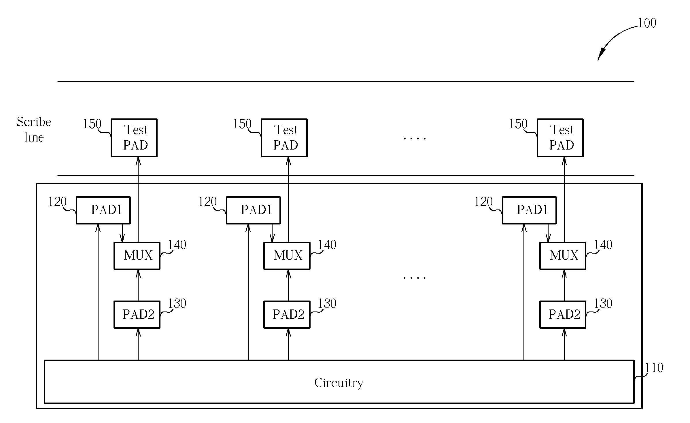
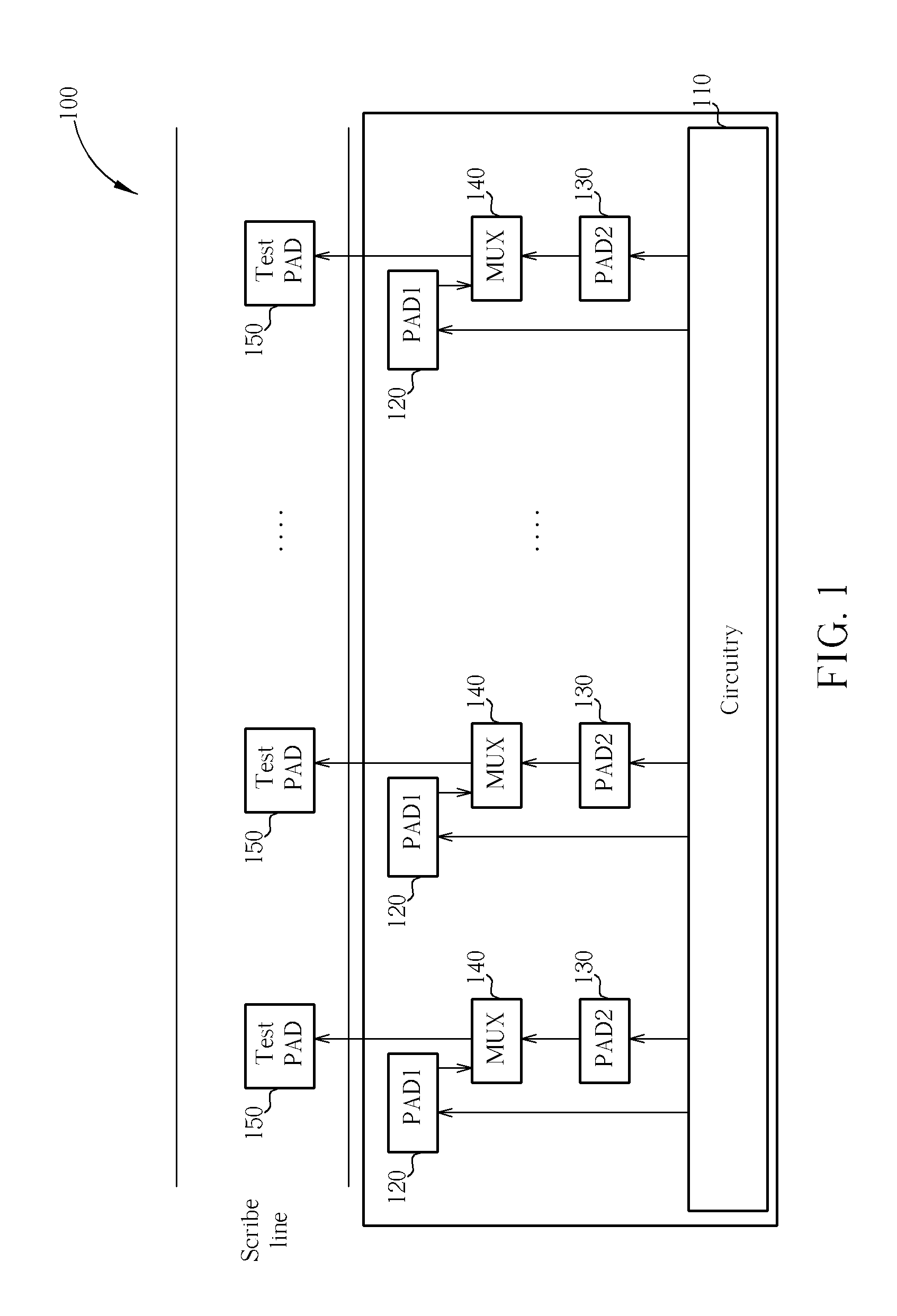
[0005]One objective of the present invention is therefore to provide an IC die structure able to simplify chip testing, and a testing method thereof. The IC die structure allows a probe card with pin counts less than the pad number of the IC die to be utilized when chip testing, thereby achieving an advantage of reduced costs. Moreover, the pad number / pad pitch of the IC die is not limited by the pitch of the conventional probe card. A high pin count IC die design is thereby available.

Problems solved by technology

A limitation of the IC design is the probe card used in wafer testing.
Since a conventional chip testing technique cannot provide high pin counts / small pitch probe card with low cost, the IC die structure is restricted and the IC designer has to make a choice between performance and production cost.

Method used


Image

  • Integrated circuit die structure simplifying IC testing and testing method thereof
  • Integrated circuit die structure simplifying IC testing and testing method thereof
  • Integrated circuit die structure simplifying IC testing and testing method thereof

Examples


Embodiment Construction

[0013]Certain terms are used throughout the description and following claims to refer to particular components. As one skilled in the art will appreciate, manufacturers may refer to a component by different names. This document does not intend to distinguish between components that differ in name but not function. In the following description and in the claims, the terms “include” and “comprise” are used in an open-ended fashion, and thus should be interpreted to mean “include, but not limited to . . . ”. Also, the term “couple” is intended to mean either an indirect or direct electrical connection. Accordingly, if one device is coupled to another device, that connection may be through a direct electrical connection, or through an indirect electrical connection via other devices and connections.

[0014]The present invention provides an IC die that can utilize less test pads than conventional IC dies, thereby allowing utilization of a probe card having larger pitch than the pad pitch o...


PUM


Abstract

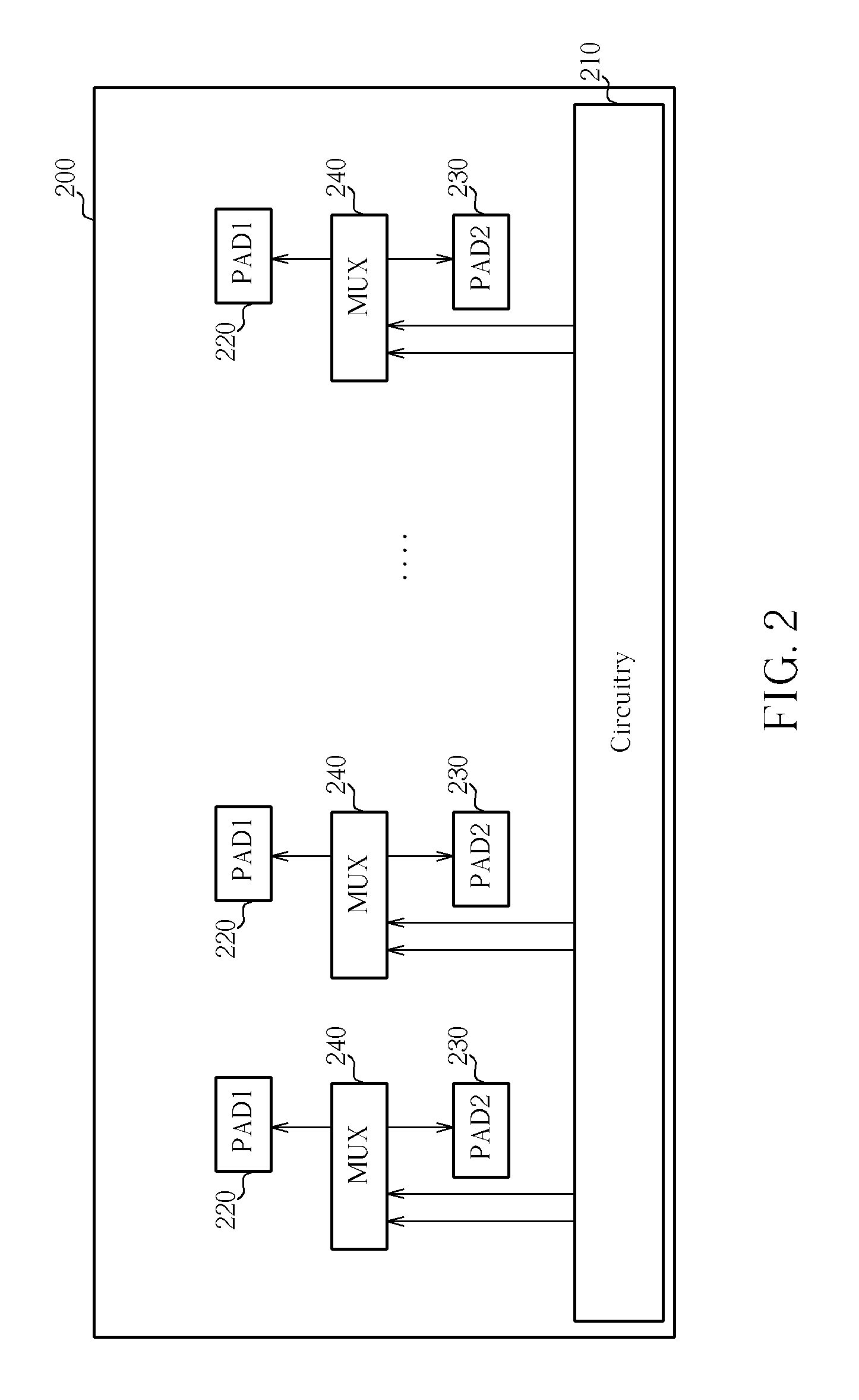
By adding multiplexing units to selectively transmit signals associated with a functional circuitry of an IC die to test pads, a probe card with less pin counts than the pad number of the IC die can be utilized for testing the functional circuitry. Therefore, the pad number / pad pitch of the IC die is not limited by the pitch of the conventional probe card. A high pin count IC die design is thereby available.

Description

BACKGROUND OF THE INVENTION[0001]1. Field of the Invention[0002]The present invention relates to an integrated circuit die structure, and more particularly, to an integrated circuit die structure able to simplify chip testing, and a testing method thereof.[0003]2. Description of the Prior Art[0004]As functionality becomes more complex and thinner and smaller sizes become available, an integrated circuit (IC) die is required to have plenty of pads and a small pad pitch. Although a current number of pads is approximately 1440 and the pad pitch has reduced to 15 μm, the current trend is still towards increasing pad numbers and reducing pad pitch. A limitation of the IC design is the probe card used in wafer testing. Since a conventional chip testing technique cannot provide high pin counts / small pitch probe card with low cost, the IC die structure is restricted and the IC designer has to make a choice between performance and production cost.SUMMARY OF THE INVENTION[0005]One objective o...

Claims


Application Information

Patent Timeline
Patent Type & Authority Applications(United States)
IPC IPC(8): G01R31/26H01L23/58
CPCG11C29/1201G11C29/48H01L22/32H01L2924/0002H01L2924/00
Inventor CHEN, PING-POCHEN, CHIEN-PIN
Owner HIMAX TECH LTD
Learn More