Neutron Generator

a technology of neutron generator and ion source, which is applied in the field of neutron generator, can solve the problems of limited collision efficiency of neutron generator using penning ion source used in logging tools, low atomic to molecular ion ratio of ion source, and relatively cumbersome, and achieves the effect of higher atomic density

Inactive Publication Date: 2009-05-28
SCHLUMBERGER TECH CORP
View PDF13 Cites 70 Cited by
  • Summary
  • Abstract
  • Description
  • Claims
  • Application Information

AI Technical Summary

Benefits of technology

[0012]The neutron generator of the present invention provides gas ionization at a much higher atomic to molecular ratio than the prior art neutron generators. This allows for small compact size designs suitable for logging tools that are used

Problems solved by technology

However, neutron generators using Penning ion sources used in logging tools suffer from limited collision efficiency and a relatively low atomic to molecular ion ratio of the ion source.
Such designs are relatively cumbers

Method used


Image

  • Neutron Generator
  • Neutron Generator
  • Neutron Generator

Examples


Embodiment Construction

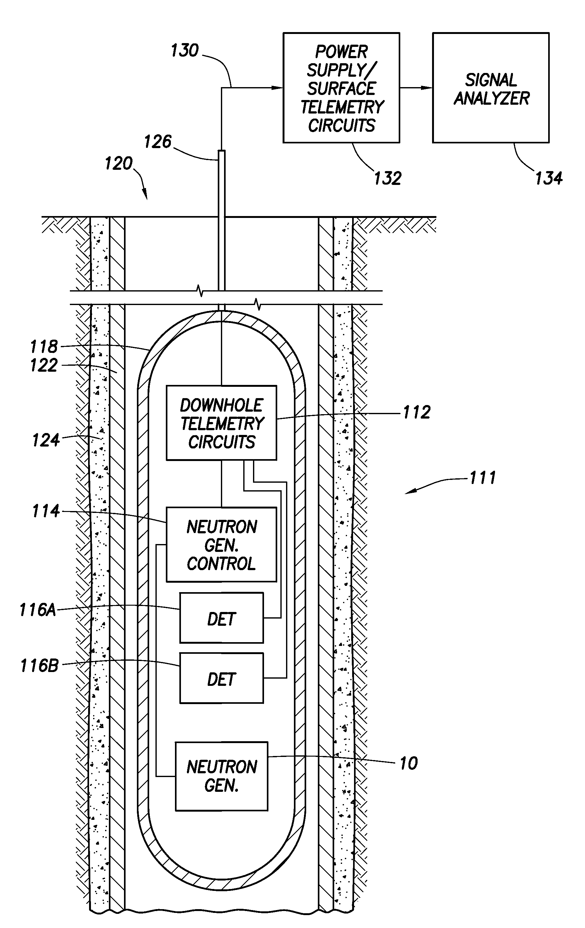
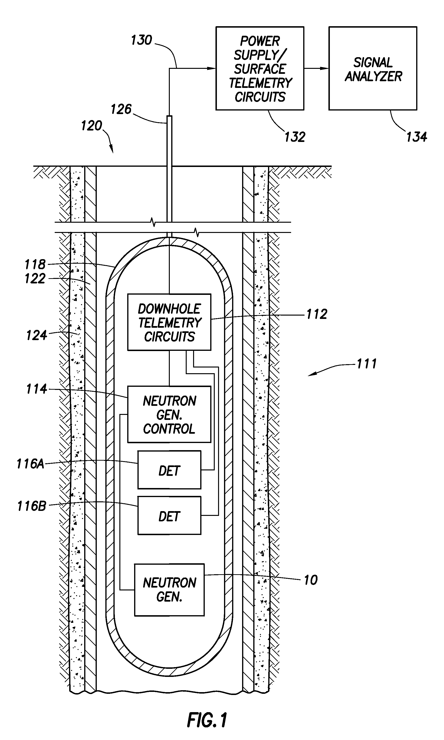
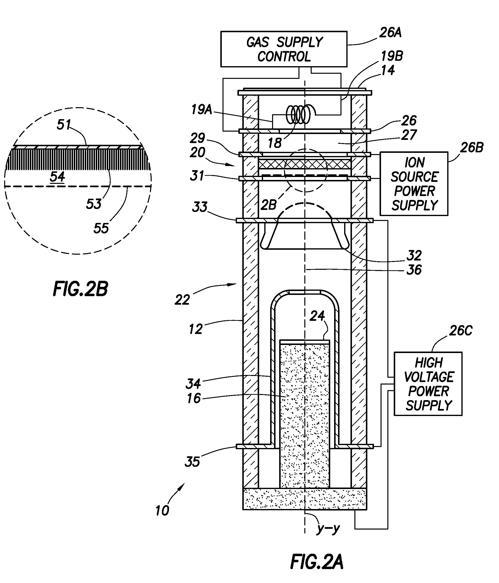
[0017]Turning now to FIGS. 1 and 2A, the neutron generator 10 in accordance with the present invention may be used as part of a logging tool 111 as shown. The neutron generator 10 includes a sealed insulating hollow cylindrical tube 12 that houses gas supply means 18, an ton source 20, an ion accelerator section 22 and a target 24 as described below in more detail. Typically, the tube 12 is enclosed in a metal housing (not shown) which is filled with a dielectric media to insulate the high voltage elements of the tube 12. The metal housing together with electrical components, e.g., downhole telemetry circuits 112, neutron generator control circuitry 114 (which include gas supply control circuitry 26A, ion source power supply circuitry 26B, and high voltage power supply circuitry 26C as described below), at least one radiation detector (for example, two shown as 116A, 116B) and possibly other system components are housed in a sonde 118 that is configured to be drawn through a borehol...


PUM


Abstract

A neutron generator includes an ion source disposed in a pressurized environment containing an ionizable gas. The ion source includes a substrate with a bundle of carbon nanotubes extending therefrom. The ends of the nanotubes are spaced from a grid. Ion source voltage supply circuitry supplies a positive voltage potential between the substrate and the grid of the ion source to cause ionization of the ionizable gas and emission of ions through the grid. An ion accelerator section is disposed between the ion source and a target. The ion accelerator section accelerates ions that pass through the grid towards the target such that collisions of the ions with the target cause the target to generate and emit neutrons therefrom. The ion source, accelerator section and target are housed in a sealed tube and preferably the carbon nanotubes of the bundle are highly ordered with at least 106 carbon nanotubes per cm2 that extend in a direction substantially parallel to the central axis of the tube. The neutron generator provides gas ionization at much higher atomic to molecular ratio that the prior art, which allows for small compact size designs suitable for logging tools that are used in space-constrained downhole environments.

Description

BACKGROUND OF THE INVENTION[0001]1. Field of the Invention[0002]This invention relates to neutron generating systems and more particularly pertains to a new and improved neutron generator especially adapted to traverse the narrow confines of a well or borehole, although useful in a variety of other applications. Since a neutron generator embodying the invention is ideally suited to the needs of well logging services, it will be described in that connection.[0003]2. The Related Art[0004]The use of a generator of high energy neutrons has been known for a long time for neutron-gamma ray or neutron-neutron logging. Neutron generators used in oil well logging tools usually require controlled low pressure atmospheres and high intensity magnetic fields. Accordingly, for illustrative purposes, the invention is described in more complete detail in connection with a neutron generator suitable for use in a well logging tool.[0005]Neutron generators usually have three major features:[0006](i) a...

Claims


Application Information

Patent Timeline
IPC IPC(8): H05H3/06G01V5/10
CPCH05H3/06H01J2201/30469B82Y99/00G01V5/10Y10S977/963
Inventor GROVES, JOEL L.
Owner SCHLUMBERGER TECH CORP
Why Eureka
Try Eureka