
Image processing device and method, program, and recording medium

a technology of image processing and recording medium, which is applied in the field of image processing devices and methods, programs, and recording media, can solve the problems of marked visual deterioration and the marked deterioration of achieve the effect of improving the detection precision of the motion vector particularly using the gradient method

Inactive Publication Date: 2009-05-28
SONY CORP
View PDF4 Cites 17 Cited by
  • Summary
  • Abstract
  • Description
  • Claims
  • Application Information

AI Technical Summary

Benefits of technology

[0009]The present invention has been made in light of such a situation, which enables the detection precision of a motion vector using the gradient method to be improved.
[0022]According to an aspect of the present invention, the detection precision of a motion vector particularly using the gradient method can be improved.

Problems solved by technology

Note however, an object pixel having a different motion from the motion of a pixel of interest or a block of interest has been mixed in this computation block in some cases, and in this case, an unlikely motion vector has been frequently detected, and consequently, the detection precision of a motion vector has markedly deteriorated.
Moreover, an image subjected to frame frequency conversion by employing the motion vector obtained as a result thereof has a possibility of marked visual deterioration being caused thereby, particularly such as occurrence of noise around the boundary of the object thereof, occurrence of discontinuity, and so forth.

Method used


Image

  • Image processing device and method, program, and recording medium
  • Image processing device and method, program, and recording medium
  • Image processing device and method, program, and recording medium

Examples


Embodiment Construction

[0141]Description will be made below regarding embodiments of the present invention with reference to the drawings.

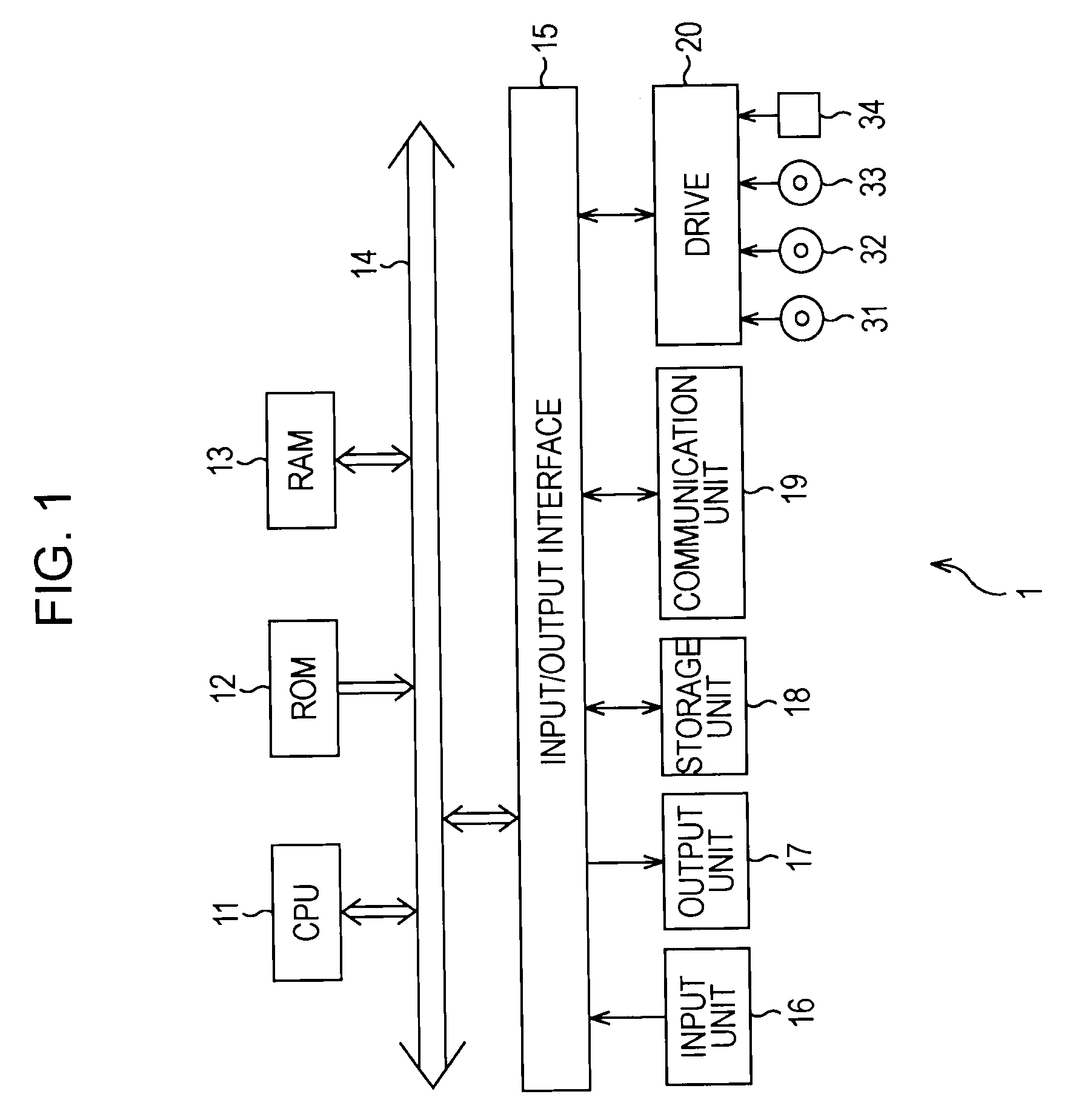
[0142]FIG. 1 represents a configuration example of a signal processing device 1 to which the present invention is applied. The signal processing device 1 is configured of a personal computer and so forth, for example. In FIG. 1, a CPU (Central Processing Unit) 11 executes various types of processing in accordance with a program stored in ROM (Read Only Memory) 12 or a storage unit 18. A program which the CPU 11 executes and data and the like are stored in RAM (Random Access Memory) 13 as appropriate. These CPU 11, ROM 12, and RAM 13 are mutually connected by a bus 14.

[0143]Also, an input / output interface 15 is connected to the CPU 11 via the bus 14. The input / output interface 15 is connected with an input unit 16 made up of a keyboard, a mouse, a microphone, and so forth, and an output unit 17 made up of a display, speakers, and so forth. The CPU 11 executes various typ...


PUM


Abstract

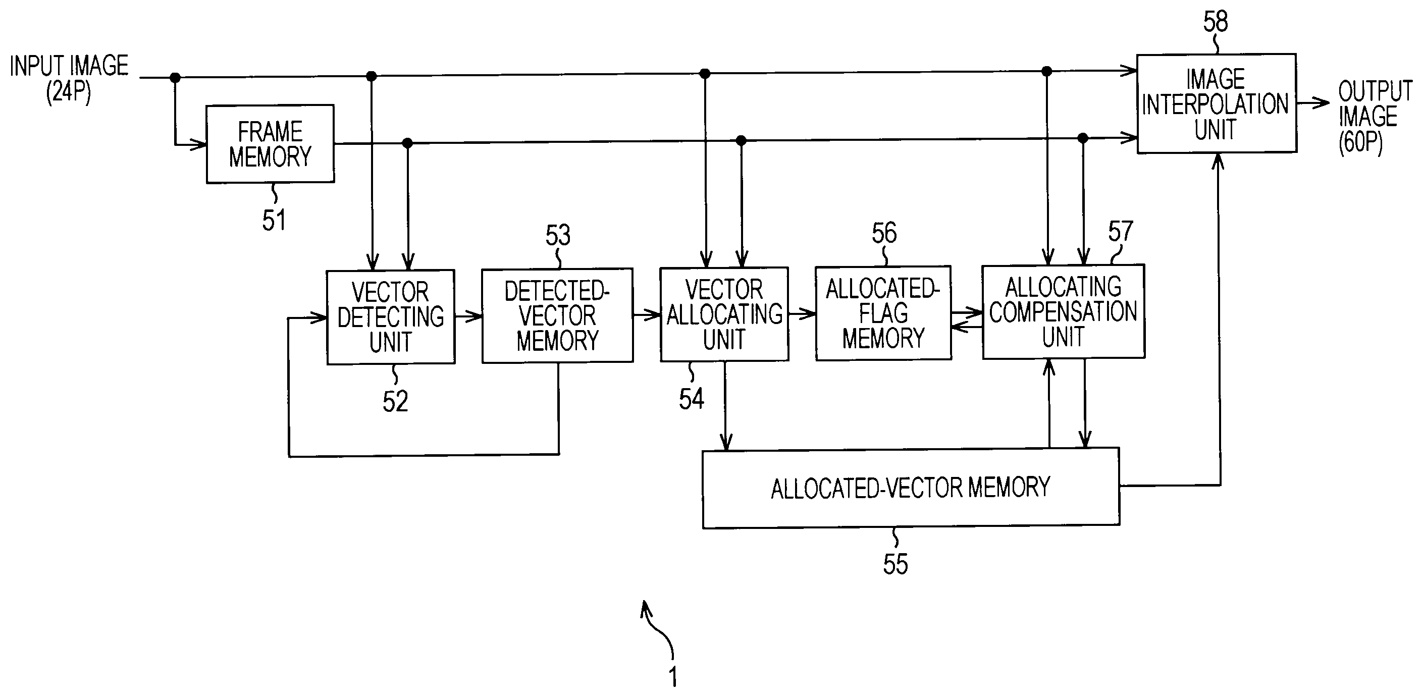
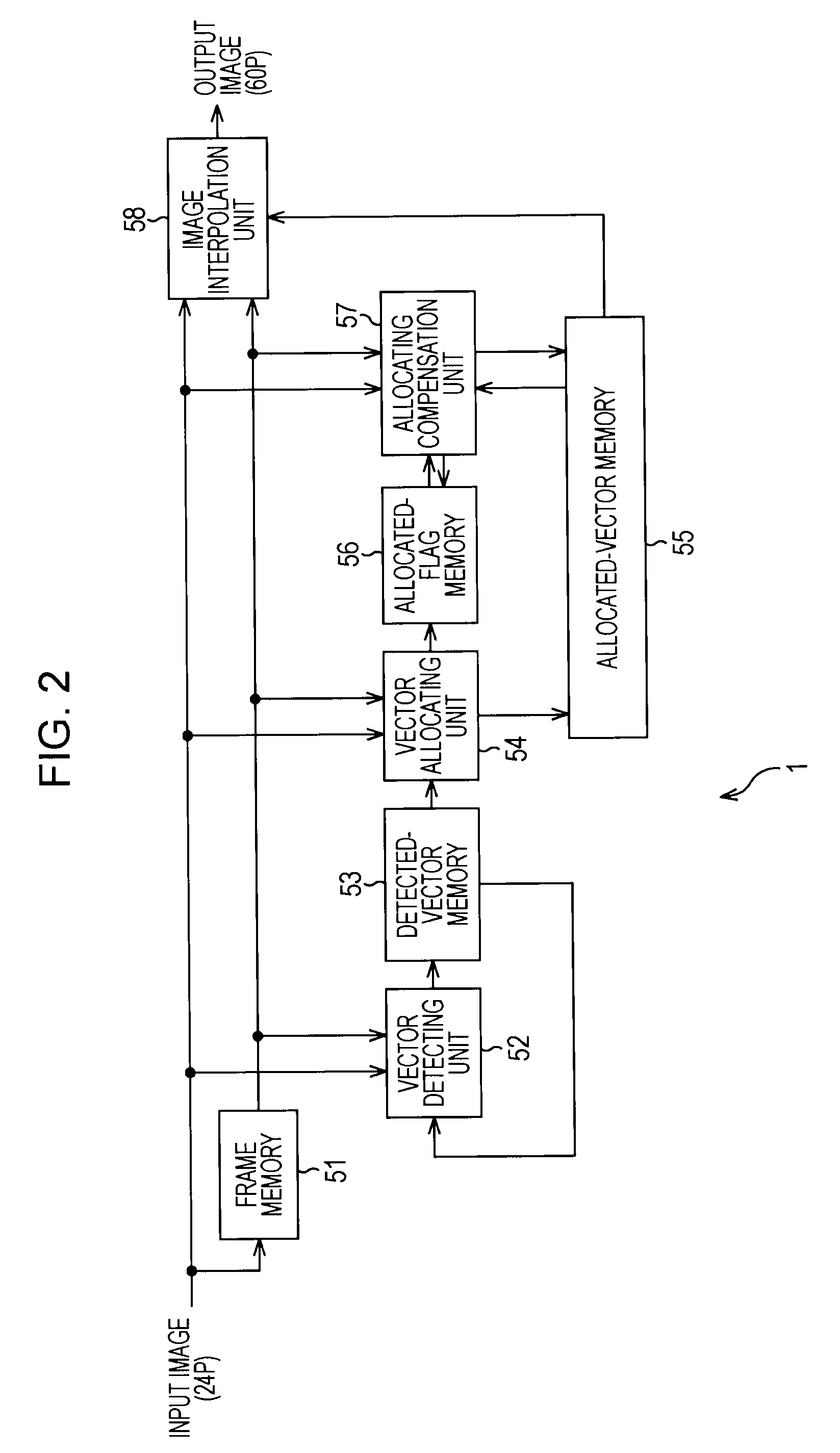
The present invention relates to an image processing device and method, a program, and a recording medium whereby the detection precision of a motion vector by the gradient method can be further improved. A counter value computing unit 451 acquires the number of valid pixels, the number of pixels having no gradient in the horizontal direction, and the number of pixels having no gradient in the vertical direction from a valid pixel number counter 441, a no-horizontal-gradient counter 442, and a no-vertical-gradient counter 443, computes the ratio between valid pixels within a computation block and one-sided gradient pixels among the valid pixels, and controls the value of a flag which a flag setting unit 452 sets in accordance with the computation results. The flag setting unit 452 sets the value of a gradient flag, and outputs the gradient flag to the subsequent stage. At the subsequent stage, gradient method computation and vector evaluation processing are executed based on the gradient flag. The present invention can be applied to a signal processing device for performing frame frequency conversion processing from a 24P signal to a 60P signal.

Description

TECHNICAL FIELD[0001]The present invention relates to an image processing device and method, a program, and a recording medium, and particularly, relates to an image processing device and method, a program, and a recording medium whereby the detection precision of a motion vector can be improved by determining the ratio of one-sided gradient pixels which have a gradient in either the horizontal direction or vertical direction of valid pixels within a computation block.BACKGROUND ART[0002]With image processing devices for performing moving image frame frequency conversion processing or moving image compression processing, it is common to perform motion detection processing on a moving image, and to perform processing using the detected motion vector (see Patent Document 1). With this motion detection processing, as a method generally employed, the block matching, iterative gradient method, and so forth are available.[0003]This iterative gradient method has a feature capable of detect...

Claims


Application Information

Patent Timeline
IPC IPC(8): G06K9/46G06T7/20H03M7/36H04N7/01H04N19/105H04N19/134H04N19/136H04N19/14H04N19/192H04N19/196H04N19/50H04N19/51H04N19/513H04N19/587H04N19/80
CPCH04N19/51G06T7/2013G06T7/223G06T7/269
Inventor KAINO, AKIHIKOHORISHI, TAKASHINAKAMURA, YUKIHIROKAWAGUCHI, KUNIOTAKAHASHI, YASUAKIYOSHIWARA, NORIFUMIMORIFUJI, TAKAFUMICHOKI, YUTA
Owner SONY CORP
Learn More