Powder coating materials

a technology of coating materials and powder, applied in coatings, layered products, transportation and packaging, etc., can solve the problems of less mean particle size, less particle more particles at the lower end of the distribution, so as to improve the handling and application properties

Inactive Publication Date: 2009-05-28
AKZO NOBEL COATINGS INT BV
View PDF37 Cites 33 Cited by
  • Summary
  • Abstract
  • Description
  • Claims
  • Application Information

AI Technical Summary

Benefits of technology

[0010]Powders of the present invention show improved handling and application properties compared with powders of the prior art.

Problems solved by technology

The smaller particles, however, give rise to problems in handling and application.
Such problems become more pronounced when the proportion of fine particles is high.
For a thin film coating, for example, generally a lower maximum particle size would be required, but the grinding process (or “micronising”) to produce a lower maximum particle size would also lead to a lower mean particle size and more particles at the lower end of the distribution, increasing the handling and application problems.
Even with such additives, however, many powders would still exhibit some application and handling problems, placing a limit on reduction in maximum particle size.

Method used


Image

  • Powder coating materials
  • Powder coating materials
  • Powder coating materials

Examples


example 1

a) Bonding of Powders D1 to H1

Preparation of Powders of the Invention D2 to H2

[0113]Five unbonded powder formulations (not according to the invention) were prepared from the base formulation VI by extrusion on a PKL 46 BUS extruder at a barrel temperature of 120° C. The extrudate was cooled down and flattened on a cooling cylinder just outside the extruder die and then kibbled to flakes. Milling was carried out under the conditions given in Table below.

TABLE 1PowderMill employedMill settingsSieve sizeDv (99)D1Hosakawa ACGSpeedN / A15.8 μmJetmill110000 rpmE1Hosakawa ACGSpeed 44 μm44.8 μmJetmill14350 rpmF1Hosakawa ACGSpeed 75 μm68.5 μmJetmill13150 rpmG1Hosakawa ACMRotor 5600 rpm106 μm90.1 μmMill 40classifier 1500 rpmH1PPSRotor 7200 rpm106 μm110.5 μm (DCMT Mill)classifier 4800 rpm1All powders manufactured by the Jetmill had to be premilled to a course powder before milling.

[0114]Particle size details (by volume) of the resulting powders are given in Table 2 below.

TABLE 2Powder% % D (v, 5...

example 2

[0127]The following Example describes the preparation and testing of further powders with a particle size distribution according to the invention. Particle size data reported was obtained using the Mastersizer X laser light-scattering device from Malvern Instruments, refractive index 1.45, absorption index 0.1.

[0128]Two powders, C6 and C20, of formulation V, were prepared by extruding as in Example 1 above and micronising the chip in an Alpine ACM5 mill. This mill utilises a twin-cyclone collection mechanism and the preparation of powders was carried out by the standard operating procedure whereby the fine fraction from the second cyclone is discarded, the product collected being the product from the base of Cyclone I. Details of the particle sizes of the powders produced are given in Table 15 below. As can be seen, powder C20, with the lower d(v,90), contains much higher proportions of sub-10 μm and sub-5 μm particles.

TABLE 15StartingPowder% % D (v, 50) (μm)D (v, 90) (μm)C64.716.82...

example 3

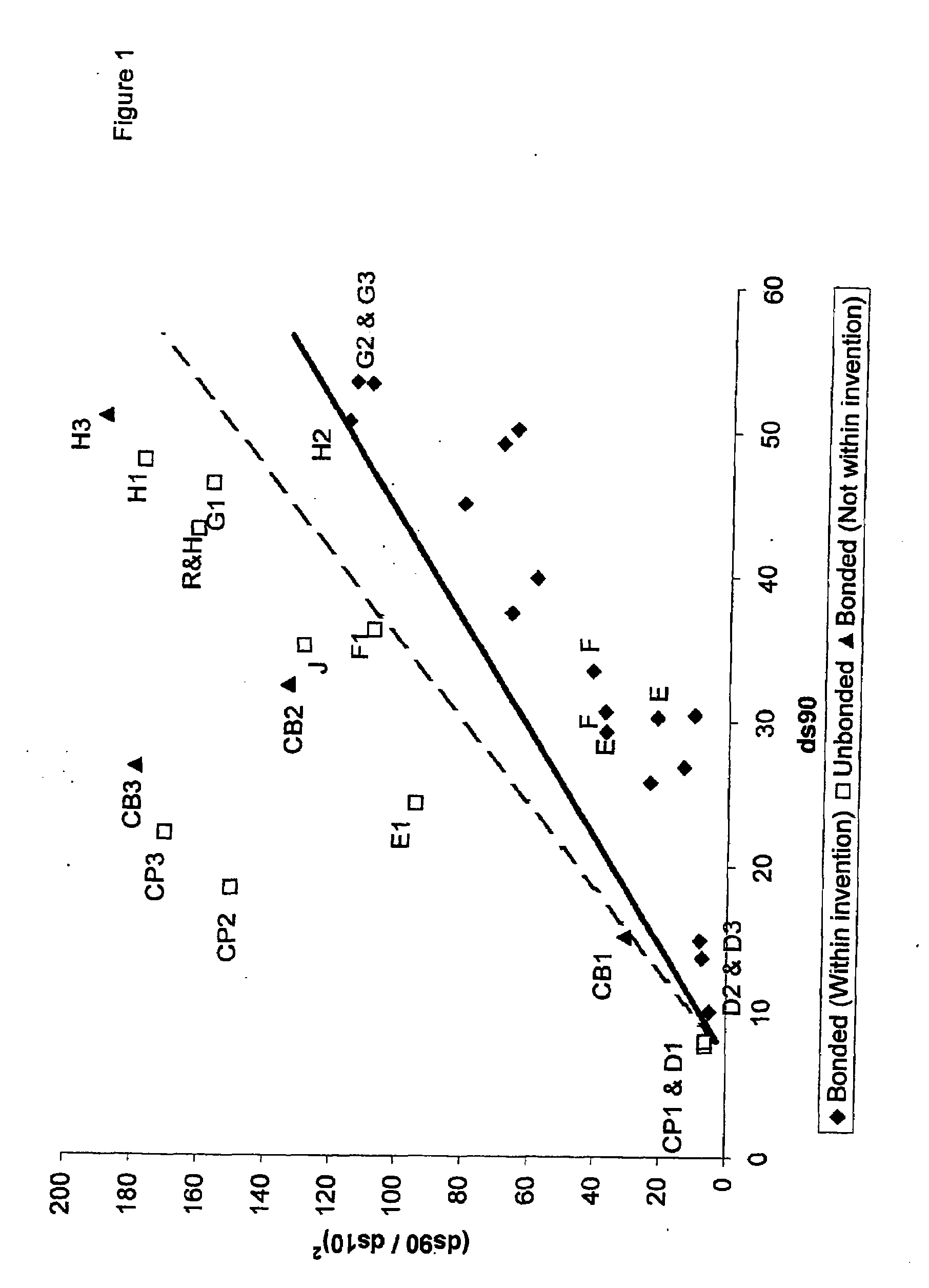
[0135]The following Example describes the preparation of further powders by the bonding process, and illustrates further how bonding conditions influence the particle size distribution of the powder produced. Bonding should be carried out such that the relationship [d(s,90) d(s,10)]2÷[d(s,90)−7]≦3.5 is met.

[0136]Further powder coating materials C1, CB2, C4, C8, C9, C11, C12 and C17 to C19 as shown in Table 20 below were prepared using the Alpine ACM5 mill under standard operating conditions as above whereby the product collected is the product from the base of cyclone 1 (identified as Cycl I in the subsequent Table), or by making efforts to collect the entire product from the mill, the operation of the mill's twin-cyclone collection system then being described as “total collect” mode (identified as “Total Col” in the Table). (In total collect mode the product from the base of both cyclones was collected, the airflow through the milling and collection system being adjusted to minimis...


PUM

PropertyMeasurementUnit
particle sizeaaaaaaaaaa
particle size distributionaaaaaaaaaa
glass transition temperatureaaaaaaaaaa

Abstract

The present invention pertains to a powder coating material comprising particles having a particle size distribution which satisfies the following equation: [d(s,90)/d(s,10)]2÷[d(s,90)−7]≦3.5 and in which d(s,90) is greater than 7 μm, d(s,90) and d(s,10) being measured in microns. The powder coatings can be obtained via a grinding-classification process or an agglomeration process. In a preferred embodiment the particles are prepared by a process which comprises mechanical fusion of a powder coating material, wherein the powder is brought to a maximum temperature in the range of from the Tg of the powder to 15° C. above the Tg, at a heating rate for at least the last 3° C., preferably at least the last 4° C., up to the maximum temperature of no more than 4° C. per minute, and after a period in the range of from 0 to 40 minutes at the maximum temperature the powder is cooled.

Description

FIELD OF THE INVENTION[0001]This invention relates to powder coating materials and to their use.[0002]Powder coatings are solid compositions which are generally applied by an electrostatic spray process in which the powder coating particles are electrostatically charged by the spray gun and the substrate is earthed. Alternative application methods include fluidised-bed processes. After application, the powder is heated to melt and fuse the particles and to cure the coating. The powder coating particles which do not adhere to the substrate can be recovered for re-use so that powder coatings are economical in use of ingredients. Also, powder coating materials are generally free of added solvents and, in particular, do not use organic solvents and are accordingly non-polluting.[0003]Powder coating materials generally comprise a solid film-forming resin, usually with one or more colouring agents such as pigments, and optionally they also contain one or more performance additives. They a...

Claims


Application Information

Patent Timeline
Patent Type & Authority Applications(United States)
IPC IPC(8): B32B5/16B29B9/00
CPCC09D5/031C09D5/033C09D163/00Y10T428/25Y10T428/2982C08L2666/54Y02P20/582
Inventor RING, JOHNSPENCER, STEVEN ANTONYCORDINER, ANDREW GEORGE
Owner AKZO NOBEL COATINGS INT BV
Why Eureka
Try Eureka