
Wire-grid metal sheet, wire grid, and method for making the wire-grid metal sheet

a wire grid and metal sheet technology, applied in the field of wire grids, wire grids, methods for making wire grids, can solve the problems of difficult to make wire grids, difficult to arrange such long and thin metal strips in parallel, and high production costs of wire grids, and achieves the effect of easy production and high precision

Active Publication Date: 2009-05-28
MURATA MFG CO LTD
View PDF6 Cites 13 Cited by
  • Summary
  • Abstract
  • Description
  • Claims
  • Application Information

AI Technical Summary

Benefits of technology

[0009]To overcome the problems described above, preferred embodiments of the present invention provide a method of making a wire-grid metal sheet and a wire grid that are designed for terahertz waves, that can be easily made with high precision, and that are inexpensive.
[0018]Since a plurality of spaced strip-shaped longitudinal members extending longitudinally and at least one cross member extending substantially perpendicular to the longitudinal members are provided, a wire grid can be made by processing a metal sheet. That is, since at least one cross member is provided, even when a thin metal sheet is processed by punching or etching, breakage and warpage of the longitudinal members is significantly reduced during the processing and during handling after processing. In addition, variations in distances between adjacent longitudinal members caused by the longitudinal members being stretched by stress imposed thereon during or after the processing are significantly reduced.
[0019]Since the cross members are preferably arranged at intervals at least about five times greater than those of the longitudinal members, a wavelength for which the cross members act as a grid is at least about five times longer than the target wavelength. Therefore, there is substantially no adverse effect on the polarizing and analyzing characteristics for the target wavelength.

Problems solved by technology

In a 100-mm-diameter wire grid, in which the length of metal strips is up to about 100 mm, it is difficult to arrange such long and thin metal strips in parallel.
That is, since tension tends to cause breakage of the metal strips and variations in distances between adjacent metal strips, it is very difficult to make the wire grid.
As a result, the wire grid is very expensive to produce.

Method used


Image

  • Wire-grid metal sheet, wire grid, and method for making the wire-grid metal sheet
  • Wire-grid metal sheet, wire grid, and method for making the wire-grid metal sheet
  • Wire-grid metal sheet, wire grid, and method for making the wire-grid metal sheet

Examples


Embodiment Construction

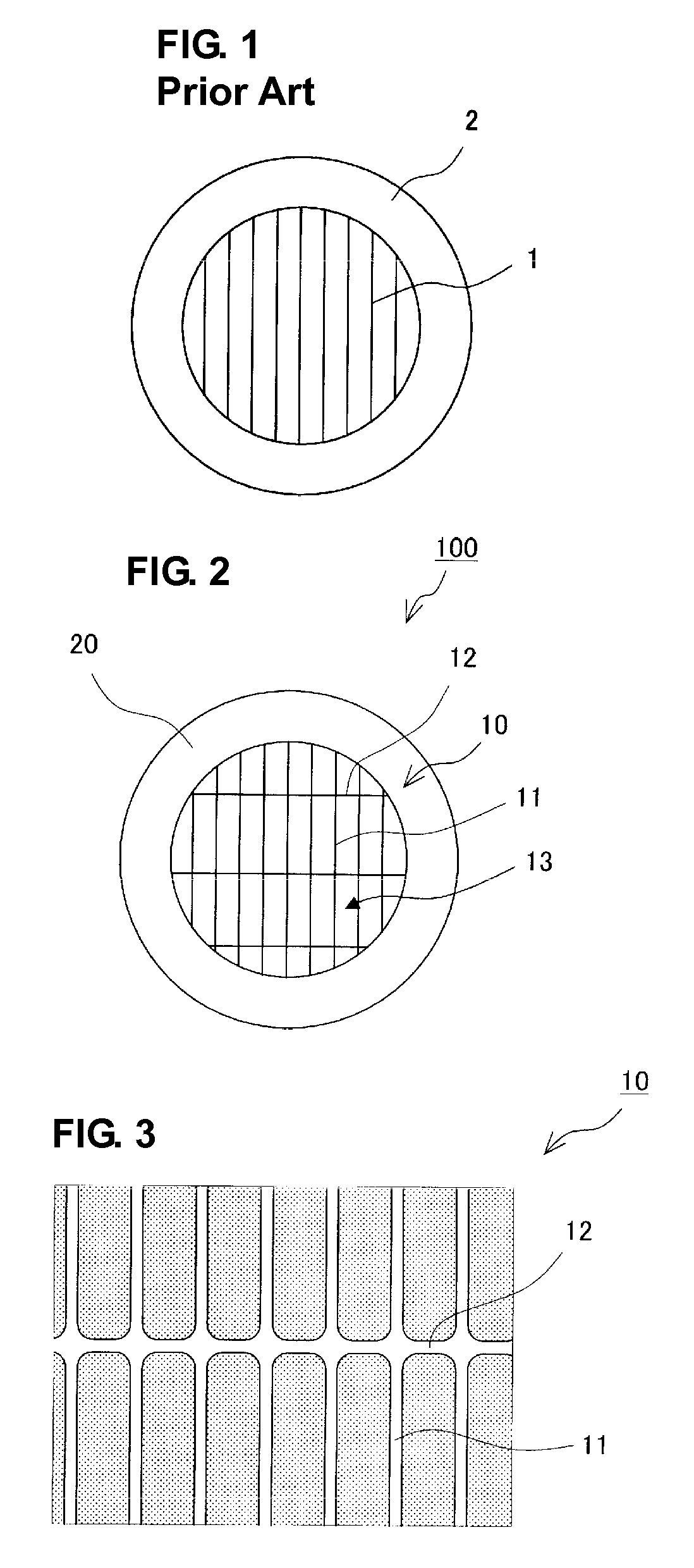
[0028]A wire-grid metal sheet of a first preferred embodiment of the present invention and a method for making a wire grid will be described with reference to FIG. 2 to FIG. 5.

[0029]FIG. 2 is an external view of a complete wire grid. A wire grid 100 is obtained by attaching a circular wire-grid metal sheet 10 to an annular frame 20. The wire-grid metal sheet 10 includes a grid portion 13 including a plurality of spaced strip-shaped longitudinal members 11 extending longitudinally and cross members 12 extending substantially perpendicular to the longitudinal members 11 and spaced apart more widely than the longitudinal members 11.

[0030]The longitudinal members 11 and the cross members 12 may slightly obliquely cross each other. In other words, the longitudinal members 11 and the cross members 12 may cross each other at substantial right angles.

[0031]The annular frame 20 supports the circular wire-grid metal sheet 10 on both sides of the wire-grid metal sheet 10 with screws in the ann...


PUM


Abstract

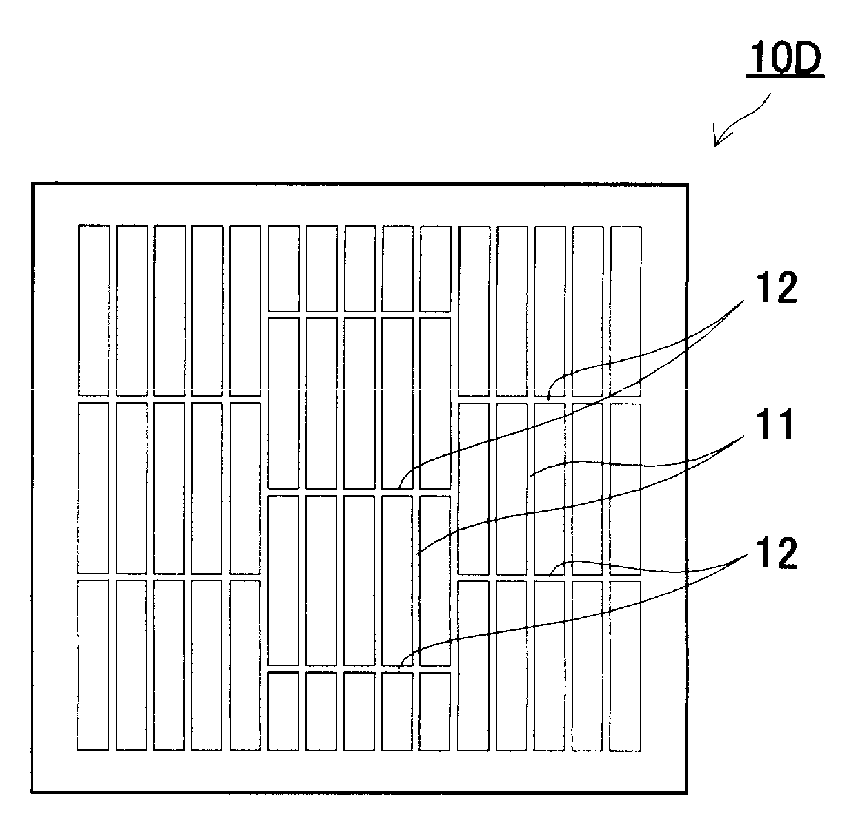
A wire-grid metal sheet includes a grid portion defined by a plurality of spaced strip-shaped longitudinal members extending longitudinally and cross members extending substantially perpendicular to the longitudinal members. A wire grid is made by attaching the wire-grid metal sheet to a frame. The cross members are arranged at intervals at least about five times greater than those of the longitudinal members. The longitudinal members and the cross members may define a lattice pattern. Alternatively, the longitudinal members or the cross members may be arranged in a staggered manner.

Description

BACKGROUND OF THE INVENTION[0001]1. Field of the Invention[0002]The present invention relates to a metal sheet used as a wire grid defining a polarizing component for terahertz waves, a wire grid having the metal sheet, and a method for making the wire grid.[0003]2. Description of the Related Art[0004]Wire grids are polarizing components commonly used for optical waves and electromagnetic waves. YOSHIHARA, Kunio “Butsuri Kogaku” (Kyoritsu Shuppan Co., Ltd., 1966 First Edition) p. 216 discloses an example of such wire grids. Japanese Unexamined Patent Application Publication No. 2003-14620 describes a wire grid included in a polarization analyzing apparatus for terahertz waves.[0005]FIG. 1 illustrates a wire grid. As illustrated in FIG. 1, the wire grid for terahertz waves is obtained by arranging long, thin metal strips 1 across a frame 2 at regular intervals. For example, the metal strips 1 may be tungsten wires with a diameter of several tens of μm and are regularly arranged at ab...

Claims


Application Information

Patent Timeline
IPC IPC(8): B32B15/00C23F1/00B21D22/00
CPCG02B5/3058Y10T428/12431Y10T428/16Y10T428/1234Y10T428/12361Y10T428/161Y10T428/218
Inventor FUJII, TAKASHIHIRAO, KAZUYUKIKITAMOTO, KENJIFUTAKU, TOSHINAGA
Owner MURATA MFG CO LTD
Learn More