Textile-Based Plate Implant and Related Methods

Active Publication Date: 2009-05-28
NUVASIVE
View PDF63 Cites 37 Cited by
  • Summary
  • Abstract
  • Description
  • Claims
  • Application Information

AI Technical Summary

Benefits of technology

[0014]According to one broad aspect of the present invention, a textile-based plate implant is provided that supports tissue ingrowth within the implanted appliance structure while limiting certain types of motion (e.g. flexion and / or extension). An implant according to the present invention is suitable for use in a variety of surgical applications, including but not limited to anterior, posterior and lateral surgical approaches directed towards the lumbar, thoracic and cervical regions of the spine. The compliant nature of the implant provides the required flexibility to support a range of physiological movements, as opposed to a completely static fusion surgery. In addition, the porosity and biocompatibility of the implant structure facilitates tissue ingrowth throughout part or all of the implant (as desired), which helps to secure and encapsulate a previously inserted complimentary implant within the affected joint, and enhance the promotion of bony fusion across the affected joint.
[0015]The implant of the present invention may have other useful purposes, such as for example ligament repair after insertion of a spinal implant. For example, after anterior spinal fusion surgery, it may be desirable or necessary to repair the anterior longitudinal ligament (ALL) to limit extension across the affected disc space. In such a case, the implant of the present invention would be fixed to adjacent vertebrae whilst spanning the fused disc space. The implant of the present invention also has the advantage of helping to maintain a bone graft or fusion cage within the disc space after implantation. This is especially true for lateral applications, since the major spinal ligaments would generally remain intact.

Problems solved by technology

As a result, some plate designs have incorporated elements which afforded limited motion across the affected joint.
While successfully implemented and widely used, these devices generally afforded limited mobility only with a commensurate trade-off of implanting a higher profile device.
Currently a gap exists in the present state of plate technology in which an extremely low profile device providing limited flexibility across the intended receiving joint while providing physical characteristics which promote optimal tissue ingrowth within the device would reside.
At times it may be advantageous to have a generally three-dimensional embroidered structure rather than a generally two-dimensional embroidered structure, but the processes by which three-dimensional embroidered structures may be formed have been complicated and not conducive to cost effective and repeatable mass production.
The drawbacks to this technique are that it makes the embroidered structure thicker where the building up had been done.
The building up only yields block-type structures and does not allow for the embroidering of curvatures.
This process is costly, with repeatability concerns where the final results and dimensions will be subject to the skill and dexterity of the individual who performs the stitching.
However, this process suffers from the same post-embroidering stitching steps in three-dimensions as the second process, and thus suffers from the same drawbacks.

Method used


Image

  • Textile-Based Plate Implant and Related Methods
  • Textile-Based Plate Implant and Related Methods
  • Textile-Based Plate Implant and Related Methods

Examples


first embodiment

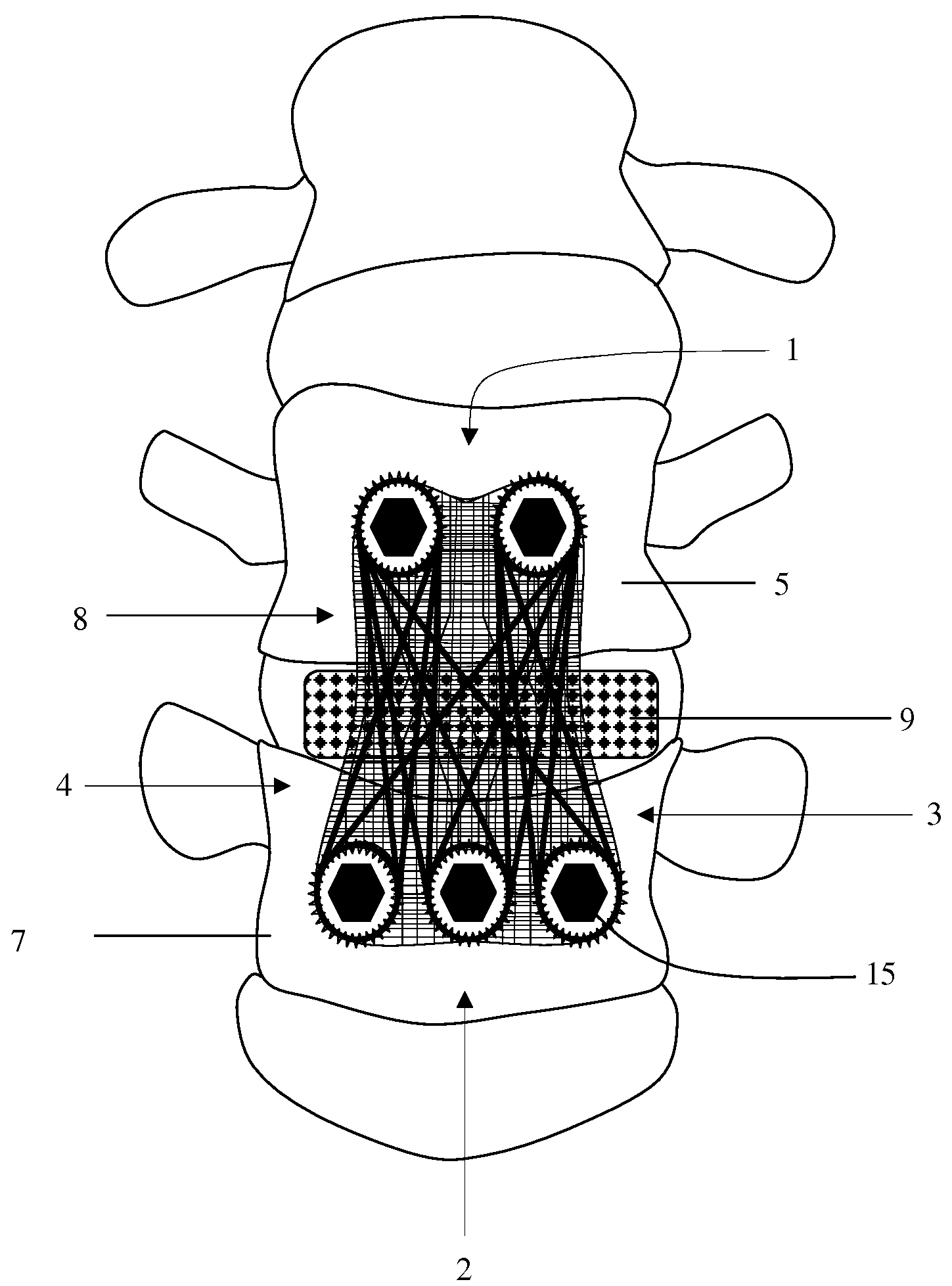
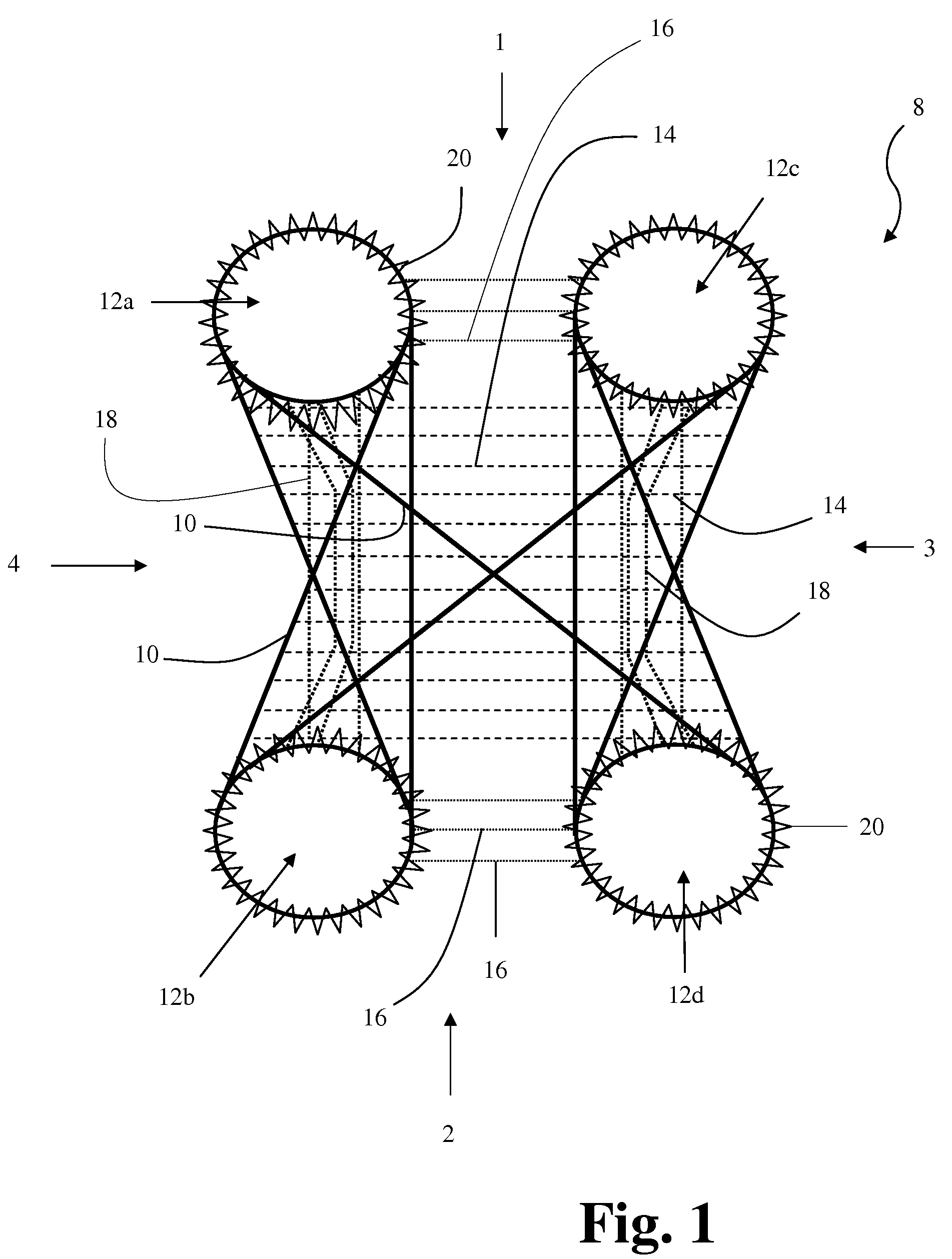
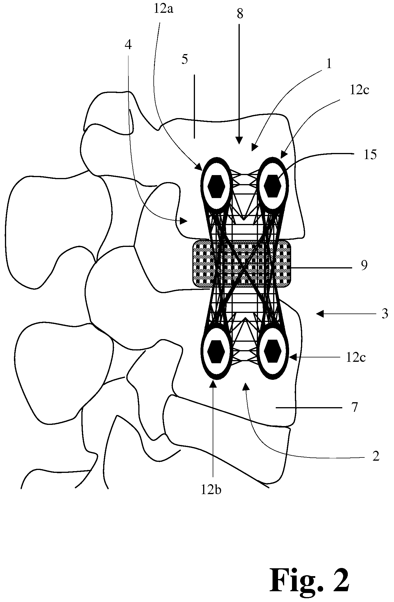
[0088]FIG. 1 illustrates an example of a textile-based plate implant 8 according to the present invention. The implant 8 is suitable for posterior, lateral or anterior insertion within the lumbar, thoracic or cervical regions of the spine. In the interest of clarity, each of the below elements are illustrated within FIG. 1 with a line quality common to that element type. Therefore, the use of dotted lines in this and other illustrations within the present application is not intended to denote various views generally attributed to the use of such lines, but rather are meant to indicate different stitching types. The implant 8 generally comprises a lattice work of filaments including load bearing filaments 10, horizontal reinforcement filaments 14, inter-aperture support filaments 16, longitudinal reinforcement filaments 18, and aperture reinforcement filaments 20, which together define the dimensions of the implant 8 including apertures 12a-12d.

[0089]The implant may be constructed f...

third embodiment

[0124]FIG. 18 illustrates the present invention comprising a generally planar textile based plate 8 with four sides 1-4 dimensioned to preferentially align five fixation apertures 12a, 12b, 12c, 12d, 12e with the intended receiving tissues 5, 7 (FIG. 19) for insertion within the lumbar, thoracic and cervical regions of the spine. In the interest of clarity, each of the below elements are illustrated within FIG. 18 with a line quality common to that element type. Therefore, the use of dotted lines in this and other illustrations within the present application is not intended to denote various views generally attributed to the use of such lines. The present device comprises a lattice work of filaments including load bearing filaments 10, horizontal reinforcement filaments 14, inter aperture support filaments 16, longitudinal reinforcement filaments 18, aperture reinforcement filaments 20 and a border filament 24 which together define the dimensions of the apertures 12a, 12b, 12c, 12d,...

second embodiment

[0156]Although shown and described in FIGS. 28 & 29, as creating a bi-modic tension feature in an embroidered structure 26 through the use of a combination of straight and zigzag load bearing filaments 50-56 and 60-62, a variety of techniques may be used to achieve the effect of a multi-modic tension feature. By way of example only, as shown in FIGS. 30-35, thread paths 112 of long stitches 114 and thread paths 116 of short stitches 118 may be used to create the effect of a multi-modic tension feature in an embroidered structure 110, according to the present invention.

[0157]FIG. 30 illustrates a backing thread 120 and a stitching thread 122 stitched together on a dissolvable substrate 124. The threads 120, 122 may be formed from any suitable material for creating an embroidered structure, including but not limited to polyester, polypropylene, polyethylene, ultra high molecular weight polyethylene (UHMWPe), carbon fiber, glass, glass fiber, polyaramide, metal, copolymers, polyketones...


PUM


Abstract

A textile-based plate implant (and related methods) that supports tissue ingrowth within the implanted implant structure and is suitable for use in a variety of surgical applications, including but not limited to anterior, posterior and lateral surgical approaches directed towards the lumbar, thoracic and cervical regions of the spine.

Description

CROSS REFERENCES TO RELATED APPLICATIONS[0001]The present application is a non-provisional patent application claiming the benefit of priority under 35 USC 119(e) from U.S. Provisional Application Ser. No. 61 / 003,752, filed on Nov. 19, 2007, U.S. Provisional Application Ser. No. 61 / 009,465, filed on Dec. 28, 2007, and U.S. Provisional Application Ser. No. 61 / 048,906, filed on Jul. 1, 2008, the entire contents of which are hereby expressly incorporated by reference into this disclosure as if set forth fully herein. The present application also incorporates by reference the following documents into this disclosure in their entireties: U.S. Pat. No. 7,338,531, issued Mar. 4, 2008 and entitled “Textile Prosthesis;” U.S. Pat. No. 7,214,225, issued May 8, 2007 and entitled “Connector;” and U.S. patent application Ser. No. 11 / 968,157, filed Dec. 31, 2007 and entitled “Using Zigzags to Create Three-Dimensional Embroidered Structures.”BACKGROUND OF THE INVENTION[0002]I. Field of the Inventio...

Claims


Application Information

Patent Timeline
IPC IPC(8): A61F2/28D05C15/00A61F2/04
CPCA61B17/7001A61B17/7059A61B17/7083A61B17/8028A61F2002/4495A61B17/8085A61F2/4455A61F2002/30578A61F2002/4435A61B17/808
Inventor REAH, CHRISTOPHERBUTCHER, PETERMCLEOD, ALAN
Owner NUVASIVE
Why Eureka
Try Eureka