
Immunoglobulin g binding pocket

a technology of immunoglobulin and binding pocket, applied in the field of biochemistry, can solve the problems of lack of generality, low phage display ability, and the inability to produce peptidic ligands in phage display

Inactive Publication Date: 2009-05-28
GE HEALTHCARE BIO SCI CORP
View PDF0 Cites 0 Cited by
  • Summary
  • Abstract
  • Description
  • Claims
  • Application Information

AI Technical Summary

Benefits of technology

[0050]Alternatively, the present polypeptide can be prepared by recombinant DNA techniques by appropriate manipulation of a host cell to provide expression of the above defined portion of a human IgG of κ-type. The manipulation can e.g. include steps to provide only a partial expression of such an IgG, or alternatively to include suitable cleaving sites for a subsequent cleaving of a ready expressed IgG or Fab fragment to isolate the desired part. Purification of the present polypeptides can for example be performed using conventional chromatography on a suitable matrix. Such techniques are also easily performed by the skilled person in

Problems solved by technology

This lack of generality is a drawback under some circumstances, since the use of Fab and F(ab′)2 fragments has increased lately due to their considerably smaller size, as compared to intact IgG molecules, while still containing the functional antigen-binding region.
In addition to the above, protein ligands of this kind are often relatively expensive to produce, they are amenable to proteolytic degradation and they are also usually sensitive to both high and low pH values.
However, phage display can only produce peptidic ligands, which suffer from the above-discussed drawbacks related to degradation.
Also, there is no guarantee as to the generality of the binding since there is commonly no knowledge as to where on the target molecule used in screening the ligand actually binds.
However a void is completely surrounded by protein atoms and therefore not accessible and therefore not appropriate for ligand binding.
However, in the ribbon drawing and stereodrawing or any other type of information disclosed, there are no suggestions of the above discussed surfaces, such as pockets, that would indicate especially useful interacting surfaces for binding purposes located on the constant region of the Fab fragment.
Consequently, the antigen used therein is too short to allow any three-dimensional structure, and consequently, it is highly improbable that those linear peptides would give rise to a pocket-shaped structure.
However finding a conserved binding pocket on the surface of an antibody is a more challenging task as compared to enzymes, which generally contain a substrate pocket related to their function.

Method used


Image

  • Immunoglobulin g binding pocket
  • Immunoglobulin g binding pocket
  • Immunoglobulin g binding pocket

Examples


example 1

Identification of the Binding Pocket According to the Invention

[0108]To identify conserved sequence patches in the constant regions of heavy and light chain sequences of human Fab-fragments of κ-type sequence homology searches using BLAST (Altschul, 1990) followed by sequence alignments using CLUSTAL W (Thompson, 1994) were performed. A total of 29 heavy chain and nine κ light chain sequences of human IgG's were identified after the BLAST search. (FIG. 2).

[0109]The highest-resolution (2.0 Å) crystal structure of κ-Fab was investigated (accession code to the Protein Data Bank 1vge, Chacko et al., 1996). The MOLCAD (program available from Tripos Associates, St. Louis, Mo.) multi channel surface tool was used to identify possible binding sites in the constant part.

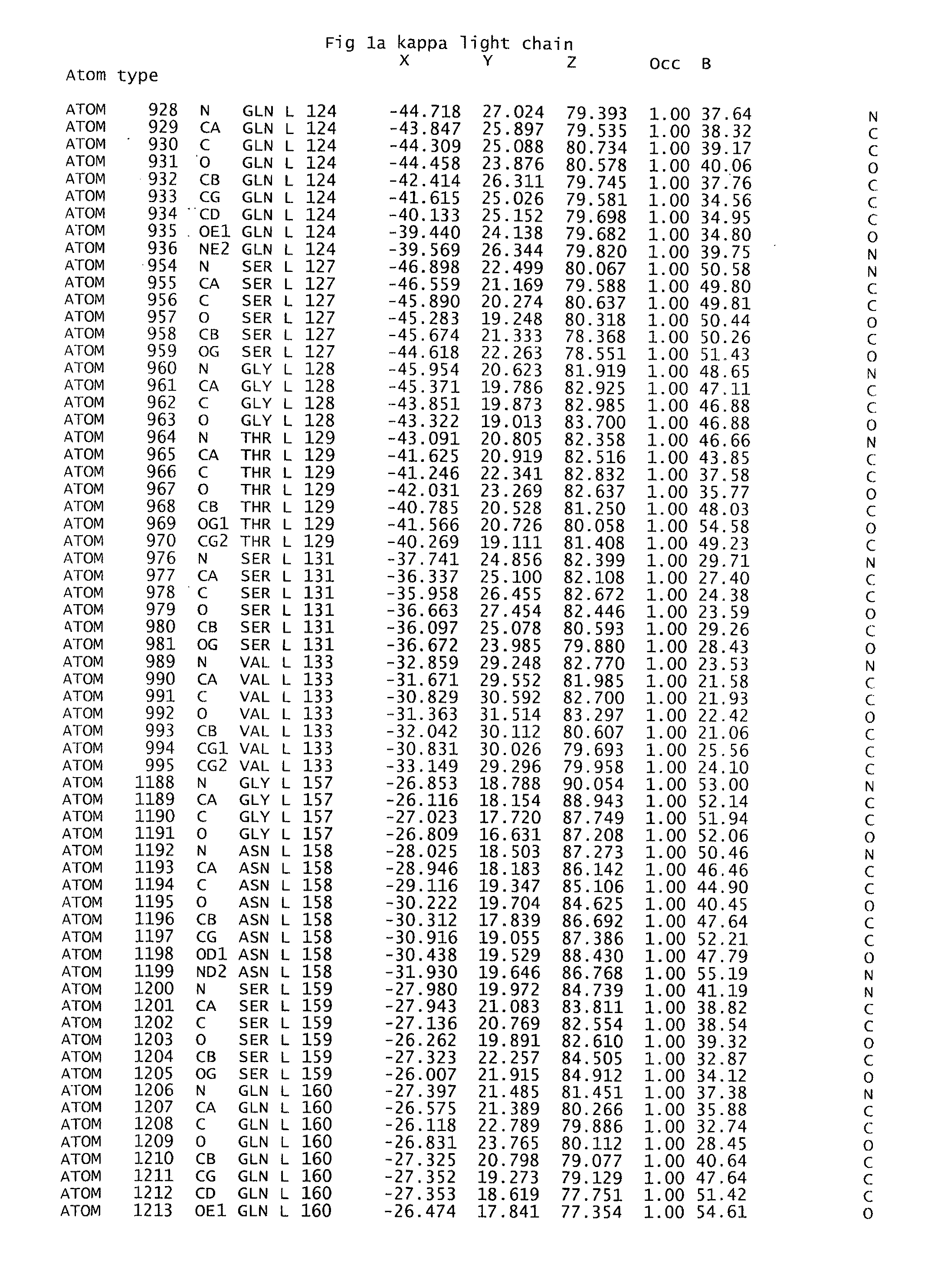
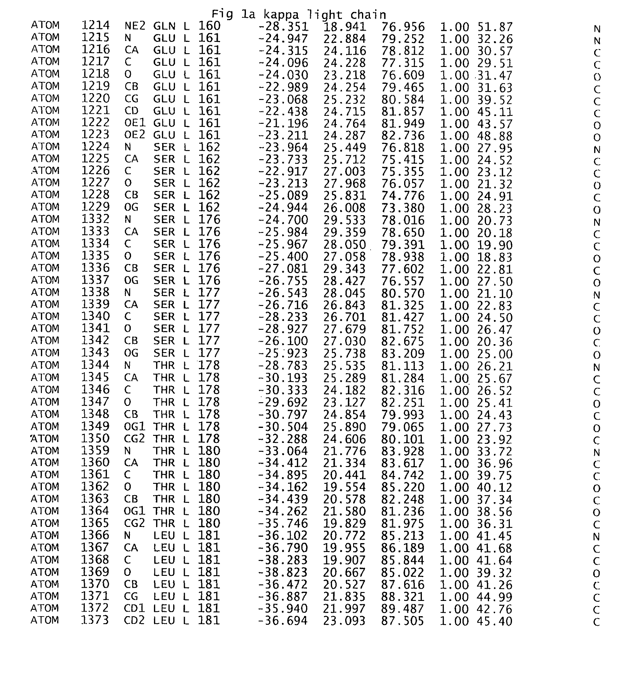
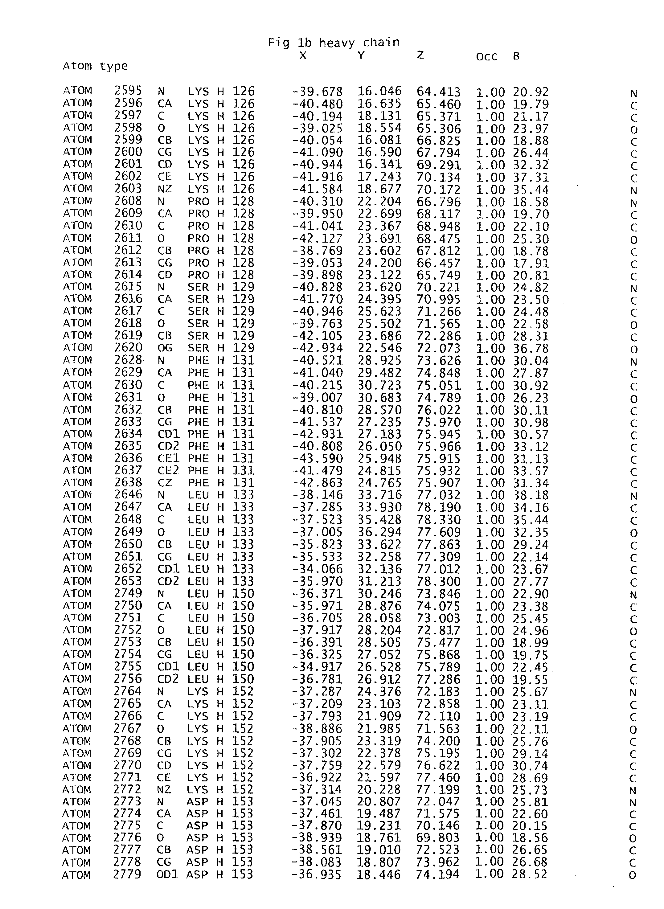
[0110]Two clefts and one pocket were identified. The pocket (FIG. 3) is located between the constant parts of the light and the heavy chain. Strictly conserved or highly conserved residues surround this pocket. Because of thi...

example 2

Use of a Fab Fragment Comprising a Binding Pocket to Identify Selectively Compounds

[0111]In the example below, the term “compound” is sometimes used to denote chemical entities tested for their ability to bind selectively to a binding pocket according to the invention. However, as appears clearly from the context, such “compounds” are not the claimed compounds discussed in the section “Detailed description of the invention” and in the appended claims.

[0112]The program package SYBYL version 6.7 (available from Tripos Associates, St. Louis, Mo.) running on an OCTANE 2-CPU 195 MHz Silicon Graphics workstation was used for all modelling. This interface provides the necessary information regarding the software and databases below.

Virtual Library

[0113]The program SELECTOR was used for filtering the molecules in MDL™ (MDL Information Systems Inc.) Available Chemical directory (ACD) allowing only for entities with a molecular weight in the range 200-500 Da and a calculated water / octanol par...

example 3

Control Experiments

Example 3a

Use of a F(ab′)2 Fragment Comprising the Binding Pocket to Verify Binding of a Selected Compound

[0123]The present example was performed with a F(ab′)2 fragment of a different specificity, i.e. a different variable part, from the one used in Example 2 above in order to verify that binding of one the selected compounds still occurred.

[0124]The testing was performed as described above in Example 2, but this time using 1 μM protein and using compound AB—0000860 as defined above in table 1. The results were positive, which implies that there is an interaction between AB—0000860 and at least two kappa Fab fragments of different specificities.


PUM

PropertyMeasurementUnit
Molecular surfaceaaaaaaaaaa

Abstract

The present invention relates to a human IgG binding pocket comprised of a first interacting surface, which originates from an IgG κ light chain, and a second interacting surface, which originates from an IgG heavy chain, which amino acids are strictly conserved between human IgGs of κ-type. The invention also embraces an isolated and purified polypeptide, which comprises said binding pocket. Further, the invention relates to various methods of using the novel binding pocket, such as in screening for identification of chemical entities capable of selective binding thereof, and in other experimental and / or virtual methods for design and / or identification of chemical entities capable of selective binding thereof.

Description

CROSS-REFERENCE TO RELATED APPLICATIONS[0001]This application is a divisional of U.S. patent application Ser. No. 10 / 532,369 filed Apr. 20, 2005, which is a filing under 35 U.S.C. § 371 and claims priority to international patent application number PCT / SE2003 / 001435 filed Sep. 12, 2003, published on May 13, 2004, as WO 2004 / 039843, which claims priority to patent application number 0203226-6 filed in Sweden on Oct. 31, 2002.FIELD OF THE INVENTION[0002]The present invention relates to the field of biochemistry, and more specifically to the identification of a novel binding site, which is strictly conserved among human IgGs of κ-type. The present invention also encompasses use of the novel binding site for identification and / or design of chemical entities capable of specific binding to such antibodies.BACKGROUND OF THE INVENTION[0003]The field of biochemistry began about a hundred years ago with a realisation that life processes involved phenomena that could be explained by the exact ...

Claims


Application Information

Patent Timeline
IPC IPC(8): G06F19/00C07D207/16C08G71/02G01N33/68
CPCC07D207/16G01N33/6854C08G71/02
Inventor AXEN, ANDREASBAUMANN, HERBERTCARREDANO, ENRIQUE
Owner GE HEALTHCARE BIO SCI CORP
Learn More