Fault-Tolerant Networks

a fault-tolerant network and fault-tolerant technology, applied in the direction of program control, specific program execution arrangement, redundant hardware error correction, etc., can solve the problems of undesirable techniques used by ohran and others, infeasible and uneconomic use of redundant network file servers instead of normal network file servers, and inability to test off-line facilities, etc., to reduce the amount of hardware required, reduce the cost of using software, and reduce the effect of hardware requirements

Inactive Publication Date: 2009-05-28
NEVERFAIL LTD +1
View PDF0 Cites 55 Cited by
  • Summary
  • Abstract
  • Description
  • Claims
  • Application Information

AI Technical Summary

Benefits of technology

[0009]A further advantage of the invention is that multiple computers can fail over to one single catcher computer, and this reduces the amount of hardware required to implement the back-up / recovery system. This has the effect of reducing costs. In addition to this, the cost of using software to install the virtual machines and associated software on the catcher computer is less than the costs of hardware that would be required to produce an equivalent physical back-up system. And, of course, the less hardware in a system, the lower the maintenance costs will be. In addition to this, managing software implemented virtual machines is easier than managing physical hardware which again leads to a cost reduction.
[0010]A yet further advantage of the invention is that an entire computing environment may be captured in software, and this provides room for the back-up / recovery system to be scaled-up easily and quickly without the need for additional expensive hardware. In addition, one can easily add additional protected computers that can be protected by the same catcher computer.
[0011]Each virtual machine (e.g., software that mimics the performance of a hardware device) is advantageously configured with its own operating system and network identity. In addition, each virtual machine within the physical catcher computer is advantageously isolated so that entirely separate computing environments can be hosted on a single physical server.
[0013]Preferably the networked computers are physical server computers. Alternatively, the networked computers may be physical workstations such as personal computers, or a mixture of servers and workstations. Thus, in addition to servers, workstations are also capable of many-to-one concurrent recovery.
[0014]The servers may be, for example, SQL servers, Web servers, Microsoft Exchange™ servers, Lotus Notes™ servers (or any other application server), file servers, print servers, or any type of server that requires recovery should a failure occur. Most preferably, each protected server computer runs a network operating system such as Windows NT™ or Windows 2000
[0015]Preferably the plurality of protected computers and the catcher computer are part of a network such as a local area network or LAN, thereby allowing transmission of information such as commands, data and programs including active applications between the protected servers and the catcher. The LAN may be implemented as an Ethernet, a token ring, an Arcnet or any other network technology, such network technology being known to those skilled in the art. The network may be a simple LAN topography, or a composite network including such bridges, routers and other network devices as may be required.

Problems solved by technology

There are, however, a number of reasons why the techniques used by Ohran and others may be undesirable.
Such one-for-one duplication may make it infeasible and uneconomic to run a redundant network file server instead of a normal network file server.
Further, the need for a redundant network to be continuously on-line to ensure that it is updated at the same time as the normal network server renders its use as an off-line facility for testing infeasible.
In addition to this, the majority of redundant networks are unable to provide protection against application failure and data corruption because they either use a common data source (e.g. the same disks) or they use live data.
Also, the majority of redundant networks are unable to provide for test and maintenance access without the risk of either network downtime or loss of resilience of the network.

Method used


Image

  • Fault-Tolerant Networks
  • Fault-Tolerant Networks
  • Fault-Tolerant Networks

Examples


first embodiment

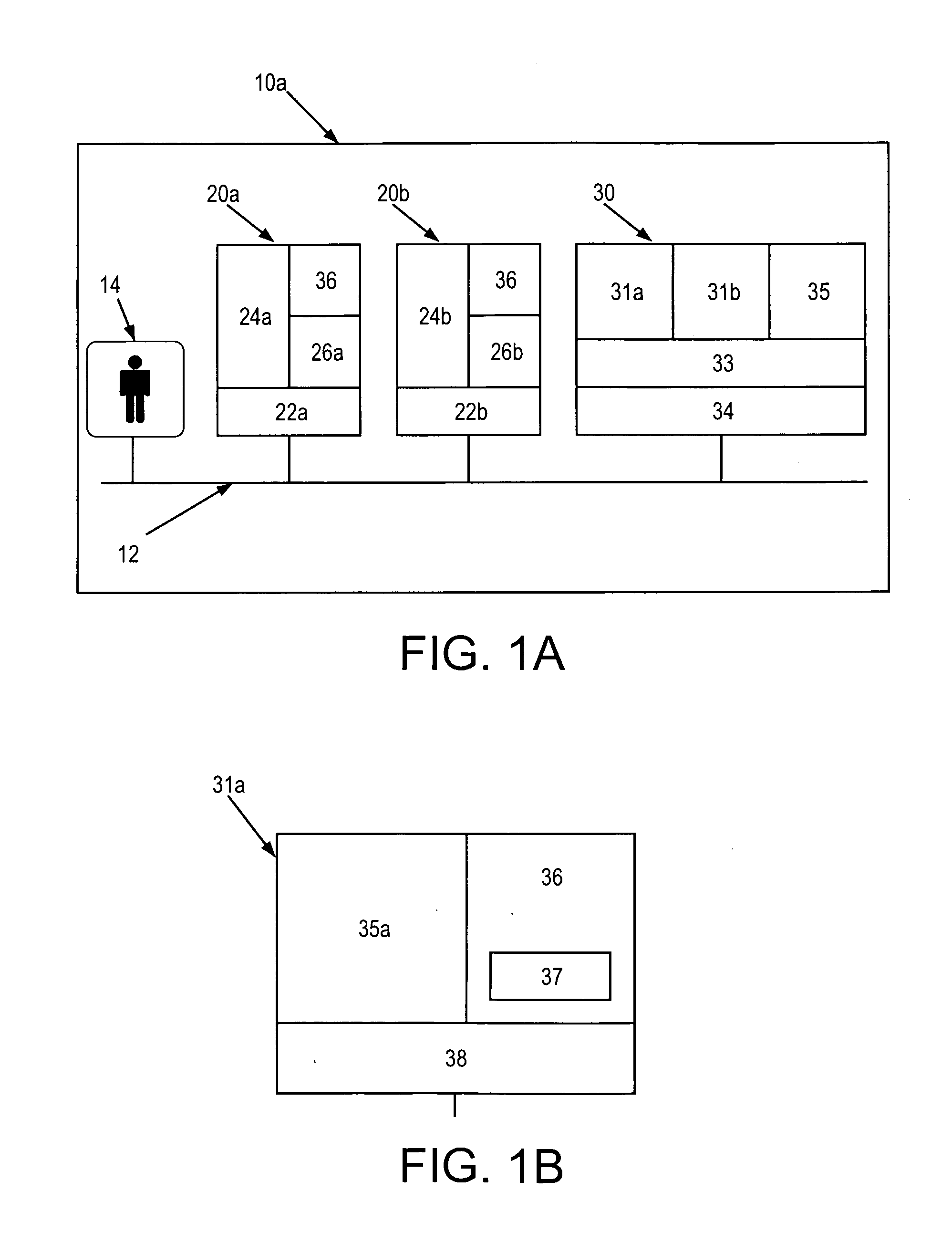
[0091]Referring to FIG. 1a, there is now described a networked system 10a suitable for implementing a method of backing-up and recovering data according to the present invention. The system 10a shown includes a first 20a, a second 20b and a third 30 computer system, which in this case are server computers. Each server 20a, 20b, 30 is connected to a network 12 through an appropriate standard hardware and software interface.

[0092]The first and second computer systems 20a,20b represent servers to be protected by the present embodiment of the invention, and are referred to herein as “protected” servers. Each protected server 20a,20b is an Intel-based platform running a respective network operating system 22a,22b (such as Windows NT™ or Windows 2000™). The protected servers 20a,20b host one or more respective application programs 24a,24b (such as Microsoft Exchange™ or Lotus Notes™) and files 26a,26b, or they may be used as a means of general network file storage. Also each protected ser...

second embodiment

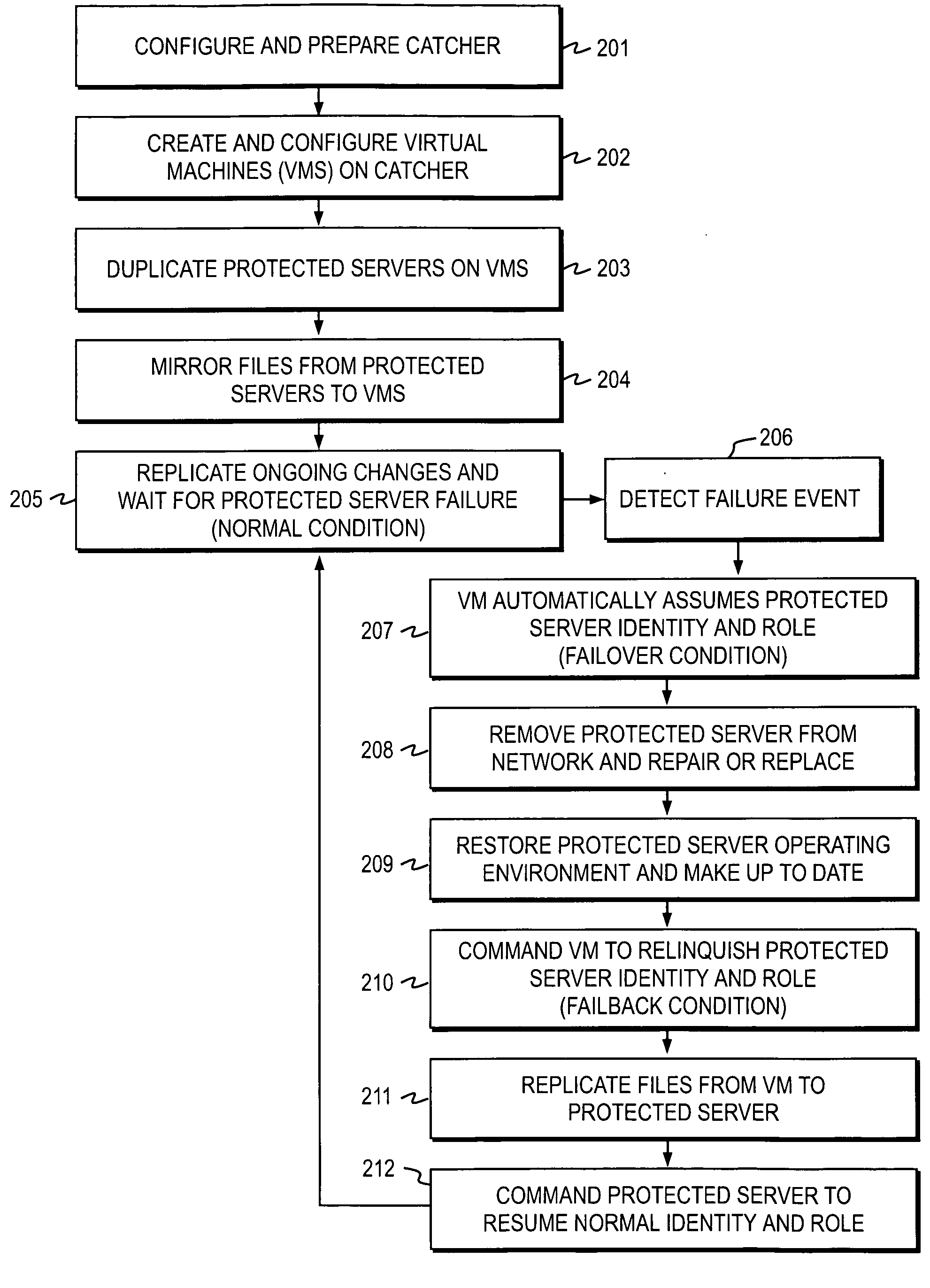
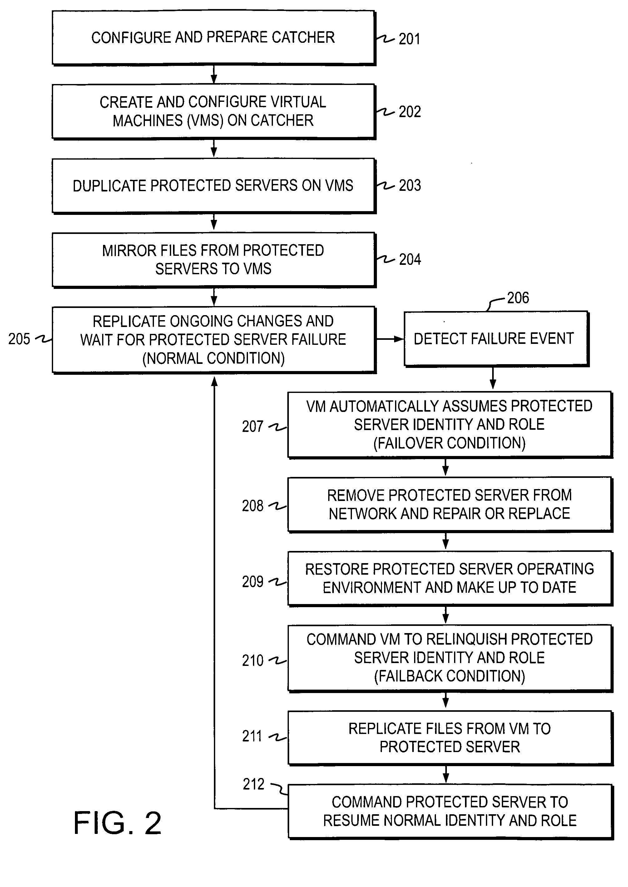
[0122]A method of backing up and recovering critical data according to the invention is now described with reference to FIG. 2 and FIGS. 4a and 4b.

[0123]In Step 401, the protected environment 10b is created by following previously described Steps 201 through 205 inclusive. That is, firstly the protected catcher 30 is configured and prepared. Secondly, the virtual machines 31 are created and configured on the protected catcher 30. Then the protected servers 20a,20b are duplicated on their respective virtual machines 31a,31b, followed by the mirroring of files from the protected servers 20a,20b to the virtual machines 31a,31b. Next, the replication of ongoing changes to the files / data residing on the protected servers 20a,20b is carried out, if required.

[0124]In Step 402, the recovery catcher 50 is built by repeating Steps 201 and 202, and thereby creating such virtual machines 51a etc as are necessary to support each of the protected servers 20a,b etc which may require remote recove...

third embodiment

[0149][The previous method described the use of the recovery environment 10c to provide a back-up and recovery system to deal with the failure of protected servers 20. However, the recovery environment 10c may also be used to protect against the failure of the entire protected environment 10b. The flow diagram in FIG. 4a shows further method Steps 430 to 433 in which a way of responding to failure of the entire protected environment 10b is described according to the invention. This circumstance may arise due to widespread equipment failure, destruction of buildings or loss of telecommunications or other causes. If such an event occurs, it may be desirable to reconstruct automatically the protected environment 10b using the information and equipment in the recovery environment 10c.

[0150]Firstly, the protected environment 10b and the recovery environment 10c are initialised in the manner as previously described in Steps 401 to 406. In Step 430, the protected environment 10b fails cau...


PUM


Abstract

Recovery systems and methods for sustaining the operation of a plurality of networked computers (20a,20b) in the event of a fault conditions are described. The basic recovery system comprises a plurality of virtual machines (31a,31b) installed on a recovery computer (30), each virtual machine being arranged to emulate a corresponding networked computer, and the recovery computer being arranged, in the event of a detected failure of one of the networked computers, to activate and use the virtual machine which corresponds to the failed networked computer (20). The recovery computer (30) may be located on the same network (12) as the networked computers (20), or alternatively on a remotely located local network in case of failure of the entire local network (12).

Description

[0001]This application is a continuation of U.S. application Ser. No. 10 / 478,960, filed on Apr. 22, 2004, which is incorporated herein by reference. U.S. patent application Ser. No. 10 / 478,960 was the National Stage of International Application No. PCT / GB02 / 02473 filed on May 27, 2002.TECHNICAL FIELD OF THE INVENTION[0002]The present invention concerns improvements relating to fault-tolerant networks and particularly, although not exclusively, to various methods, systems and apparatus for the back-up of critical data by mirroring multiple critical computers on corresponding virtual machines which are installed on a single physical back-up computer.BACKGROUND TO THE INVENTION[0003]Enterprises around the world require ways to protect against the interruption of their business activities which may occur due to events such as fires, natural disasters, or simply the failure of server computers or workstations that hold business-critical data. As data and information may be a company's mo...

Claims


Application Information

Patent Timeline
Patent Type & Authority Applications(United States)
IPC IPC(8): G06F15/16G06F11/20
CPCG06F11/2025G06F11/2048G06F11/2038G06F11/203
Inventor WING, KEITHFITZPATRICK, CHRISTOPHERSENF, WOUTER
Owner NEVERFAIL LTD
Why Eureka
Try Eureka