Exhaust air dryer with a heat pump and a first fan

a technology of exhaust air dryer and heat pump, which is applied in the direction of drying machines, washing machines, textiles and papermaking, etc., can solve the problems of increasing the installation cost of a heat pump in an exhaust air dryer, and achieves the effects of increasing the flow of supply air, facilitating the operation of the dryer, and quick heating of the supply air

Inactive Publication Date: 2009-06-04
BSH BOSCH & SIEMENS HAUSGERAETE GMBH
View PDF4 Cites 16 Cited by
  • Summary
  • Abstract
  • Description
  • Claims
  • Application Information

AI Technical Summary

Benefits of technology

[0021]The inventive exhaust air dryer is advantageous in that the heat exchanger of the heat pump can operate very efficiently, in particular in an energy-efficient manner. Moreover, the invention provides for a quick heating of the supply air. To this end, a flow of supply air can be suitably varied by the use of two fans. For instance, the use of a single fan allows a small flow of supply air to be heated up to a desired temperature. If this is achieved, the flow of supply air can be increased by connecting an additional fan.

Problems solved by technology

The installation of a heat pump in an exhaust air dryer is however associated with considerably more effort, since in an exhaust air drier with a heat pump, the condenser and evaporator, in the event of heat recovery from the exhaust air of the dryer, are clearly functionally separated from one another and also have to be connected to the air ducts.
This is usually due to the costs relating to the size of the heat exchangers and thus the efficiency thereof.

Method used


Image

  • Exhaust air dryer with a heat pump and a first fan
  • Exhaust air dryer with a heat pump and a first fan
  • Exhaust air dryer with a heat pump and a first fan

Examples


Embodiment Construction

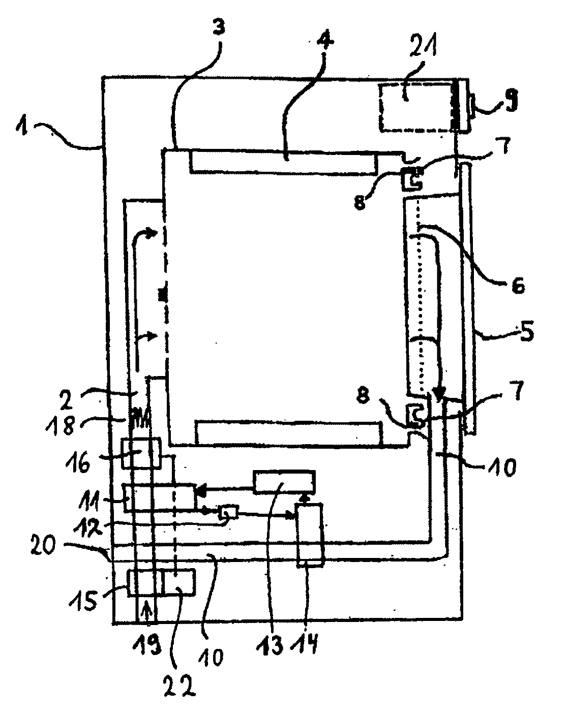
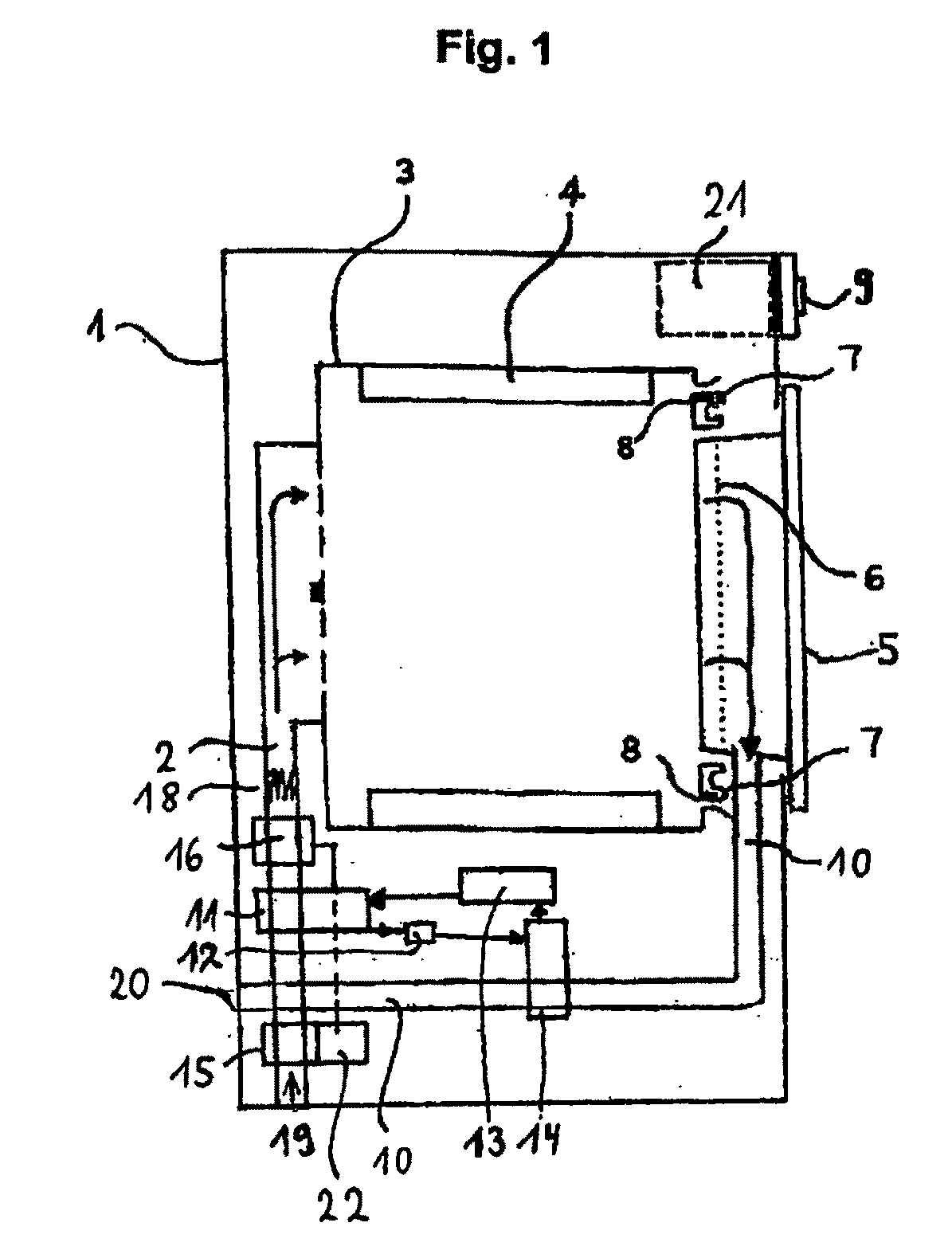
[0025]The dryer illustrated in FIG. 1 has a drum 3 which can be rotated about a horizontal axis as a drying compartment 3, within which attachments 4 for moving laundry during the rotation are fastened. Supply air is taken in from a supply air inlet 19 by means of a first fan (V1) 15 and after passing through the condenser 11, which is the heat source 11 of a heat pump 11,12,13,14, is pushed into the drying compartment 3 by means of a second fan (V2) 16. In the embodiment illustrated in FIG. 1, the supply air is heated up by means of the condenser 11 and a heater 18 (embodied here as an electrical resistance heater 18) and is guided into the drum 3 as heated supply air.

[0026]The heat transmitted by the condenser 11 originates from the evaporator 14, in which the warm air loaded with moisture which comes from the drum 3 is cooled by evaporating a coolant. After passing through the evaporator 14, the cooled air is fed to the exhaust air outlet 20 by way of the exhaust air duct 10. It ...


PUM


Abstract

The invention relates to an exhaust air dryer with a drying compartment for objects to be dried, a supply air duct upstream of the drying compartment, a first fan for the supply of process air from a supply air inlet to the drying compartment and to an exhaust air outlet, an exhaust air duct between the drying compartment and the exhaust air outlet and a heat pump, with a heat sink in the exhaust air duct and a heat source in the supply air duct, characterized in that the first fan in the supply air duct is arranged between the supply air inlet and the heat source and a second fan in the supply air duct is arranged between the heat source and the drying compartment.

Description

BACKGROUND OF THE INVENTION[0001]The invention relates to an exhaust air dryer with a drying compartment for objects to be dried, an supply air duct upstream of the drying compartment, a first fan for the supply of process air from a supply air inlet to a drying compartment and to an exhaust air outlet, an exhaust air duct between the drying compartment and the exhaust air outlet and a heat pump with a heat sink in the exhaust air duct and a heat source in the supply air duct.[0002]Such an exhaust air dryer emanates from a short extract relating to the patent publication JP 2004 089415 A which can be taken from the database “Patent Abstracts of Japan”.[0003]A tumble dryer is generally operated as an exhaust air dryer or condensation dryer. An exhaust air dryer only provides a flow of heated process air, which is routed once through the laundry placed in a drying compartment, absorbs the moisture from the laundry and then purges it out of the exhaust air dryer. Such purging is genera...

Claims


Application Information

Patent Timeline
Patent Type & Authority Applications(United States)
IPC IPC(8): F26B19/00D06F58/04
CPCD06F58/206D06F58/20
Inventor GRUNERT, KLAUSNAWROT, THOMASSTEFFENS, GUENTERSTOLZE, ANDREAS
Owner BSH BOSCH & SIEMENS HAUSGERAETE GMBH
Why Eureka
Try Eureka