Stator of a dynamoelectric machine equipped with temperature detection

Active Publication Date: 2009-06-04
SIEMENS AG
View PDF9 Cites 38 Cited by
  • Summary
  • Abstract
  • Description
  • Claims
  • Application Information

AI Technical Summary

Benefits of technology

[0017]According to another advantageous feature of the present invention, the mounting strip may be made of rigid material and allows simple plug assembly of the temperature sensor between the phase intermediate layers, i.e., for example, a two-layer phase separator, particularly in t

Problems solved by technology

If cooling is insufficient, the operating behavior of the dynamoelectric machine deteriorates, and may lead to operational failure.
This approach is inadequate as it fails to ascertain th

Method used


Image

  • Stator of a dynamoelectric machine equipped with temperature detection
  • Stator of a dynamoelectric machine equipped with temperature detection

Examples


Embodiment Construction

[0021]Throughout all the figures, same or corresponding elements may generally be indicated by same reference numerals. These depicted embodiments are to be understood as illustrative of the invention and not as limiting in any way. It should also be understood that the figures are not necessarily to scale and that the embodiments are sometimes illustrated by graphic symbols, phantom lines, diagrammatic representations and fragmentary views. In certain instances, details which are not necessary for an understanding of the present invention or which render other details difficult to perceive may have been omitted.

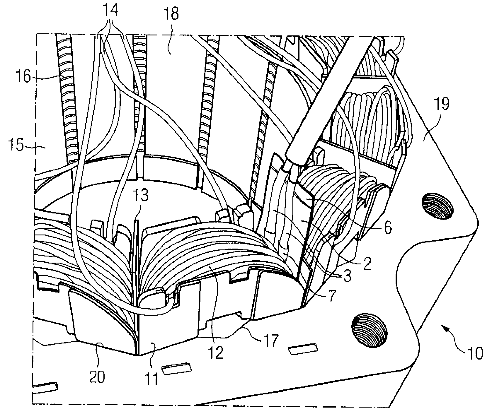
[0022]Turning now to the drawing, and in particular to FIG. 1, there is shown a perspective view of part of a stator according to the present invention, generally designated by reference numeral 10. The stator 10 has a stator body and a winding system which is attached to the stator body and is formed by tooth-wound coils 12. It is to be understood that the principles descri...


PUM

PropertyMeasurementUnit
aaaaaaaaaa

Abstract

A stator for a dynamoelectric machine includes a stator body having slots and a winding system positioned in the slots of the stator body and having coils terminating in winding heads on end faces of the stator body, wherein each slot receives different coil sides of neighboring coils. Arranged between the coil sides in at least one of the slots is a temperature sensor to ascertain a temperature in the stator, in particular between the coil sides of the winding system in the slots of the stator.

Description


Claims


Application Information

Patent Timeline
Owner SIEMENS AG
Why Eureka
Try Eureka