Self-calibrating optical feedback system in a laser mouse

Active Publication Date: 2009-06-04
PIXART IMAGING INC
View PDF9 Cites 13 Cited by
  • Summary
  • Abstract
  • Description
  • Claims
  • Application Information

AI Technical Summary

Benefits of technology

[0006]Embodiments of an apparatus are also described. The apparatus includes means for emitting coherent light. The apparatus also includes means for splitting the coherent light to produce a reflected beam and tracking beam, means for det

Problems solved by technology

However, using a laser in an optical navigation device poses hazards with respect to damage to vision.
The possibility for vision damage is made more uncertain, and potentially more dangerous, by the effects of external influences which may alter the laser output characteristics, in addition to the inherent minor differences in the characteristics of individual coherent light sources.
Thus, coherent light sources emit light beams of different output beam power, even when the same current value is driving each coherent light source, making it difficult to ensure operation of lasers below a common eye-safety threshold.

Method used


Image

  • Self-calibrating optical feedback system in a laser mouse
  • Self-calibrating optical feedback system in a laser mouse
  • Self-calibrating optical feedback system in a laser mouse

Examples


Embodiment Construction

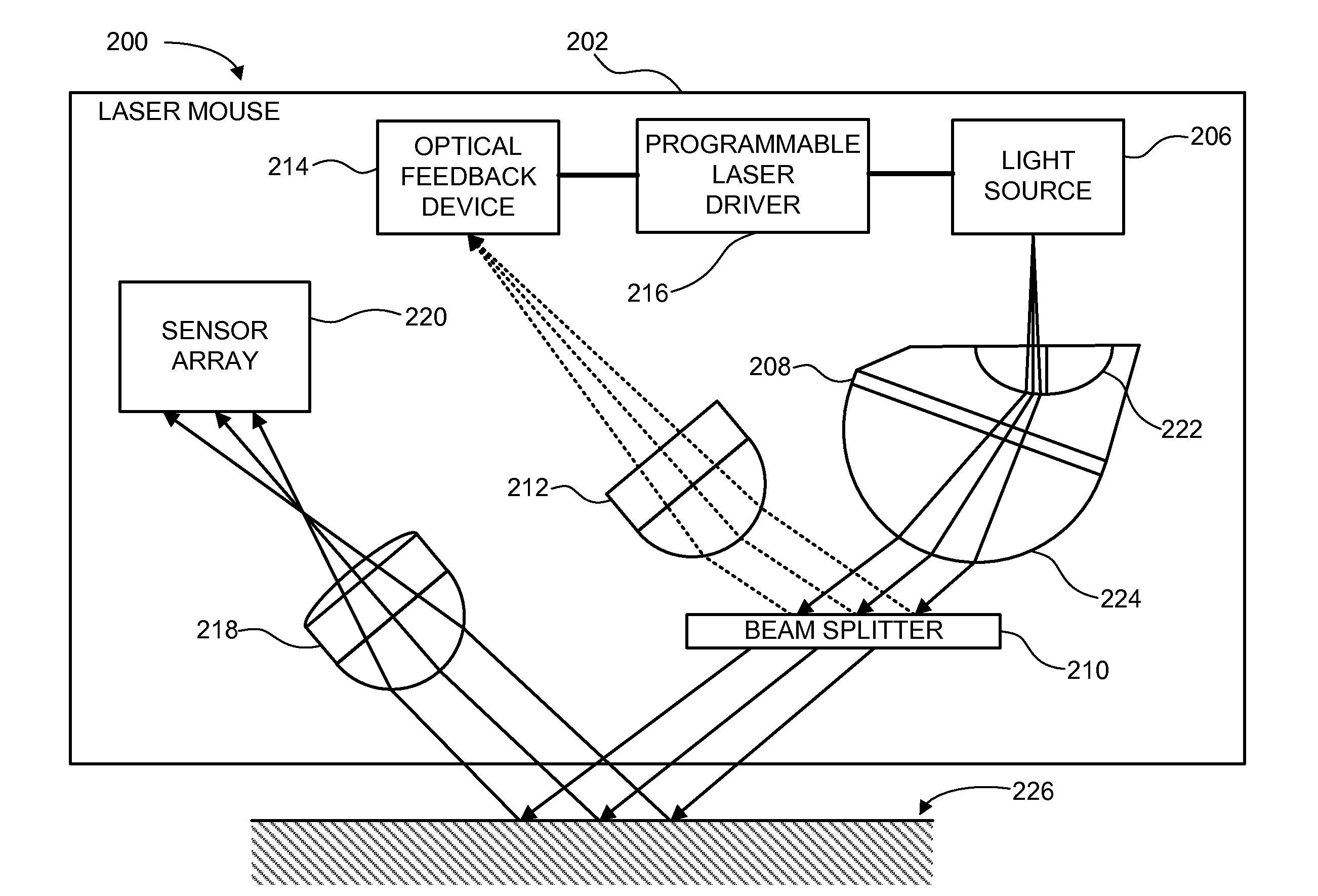
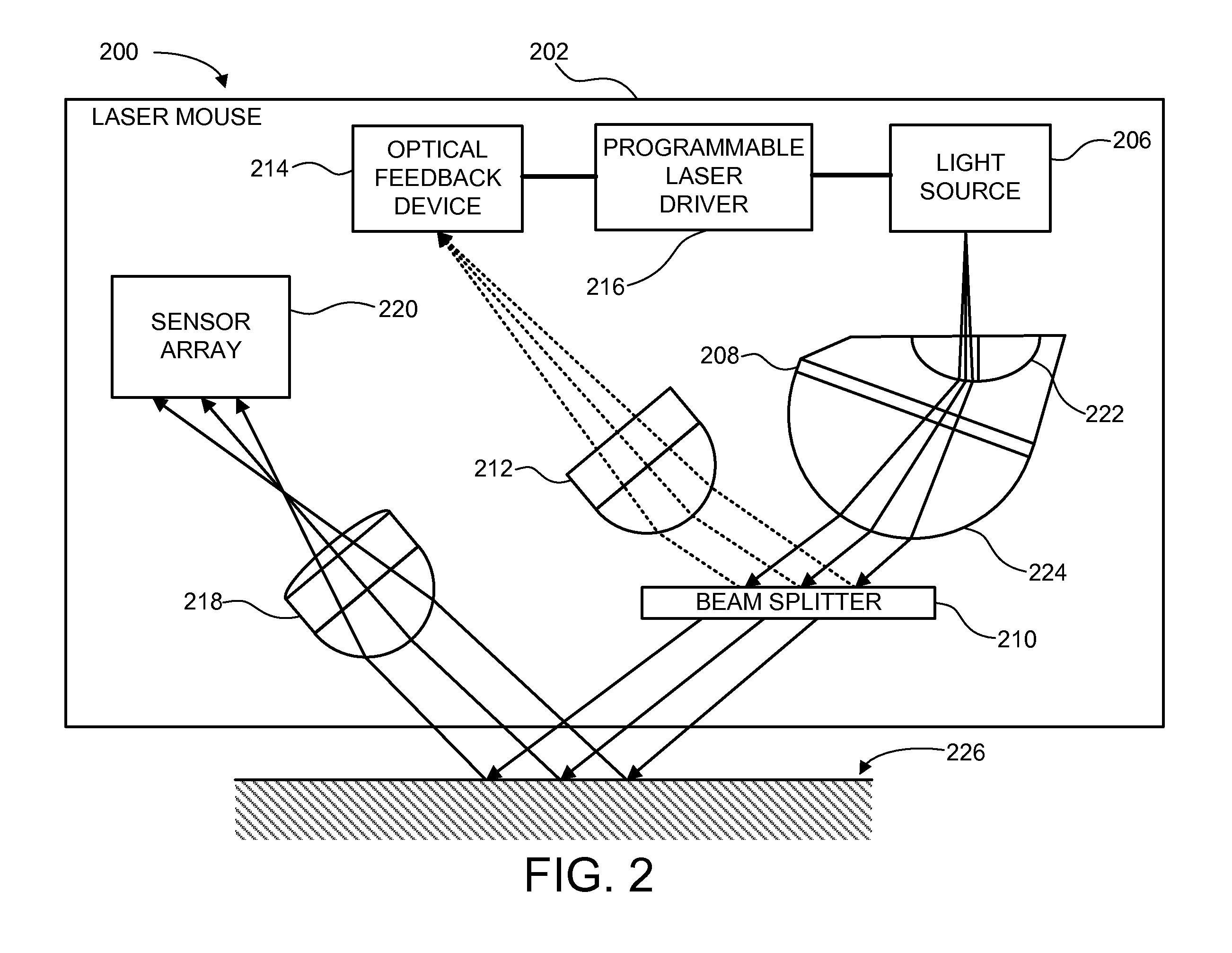
[0016]FIG. 2 depicts a schematic block diagram of one embodiment of an optical tracking system 200 with a self-calibrating optical feedback system. The illustrated optical tracking system 200 includes a laser mouse 202, and a tracking surface 226. Although certain component parts are shown in conjunction with the optical tracking system 200 of FIG. 2, other embodiments may include fewer or more component parts, or equivalent parts to perform fewer or more tracking and feedback functions.

[0017]The depicted laser mouse 202 includes a light source 206, an illumination lens 208, a beam splitter 210, a converging lens 212, an optical feedback device 214, a programmable laser driver 216, an imaging lens 218, and a sensor array 220.

[0018]The light source 206 emits a light towards the illumination lens 208. In one embodiment, the light source 206 is a light emitting diode (LED). In another embodiment, the light source 206 is a laser. Alternatively, the light source 206 may be another type o...


PUM


Abstract

A self-calibrating optical feedback system for an optical navigation device. The self-calibrating optical feedback system includes a light source, an illumination lens, a beam splitter, and an optical feedback device. The illumination lens is coupled relative to the light source. The light source emits light based on a programming current. The illumination lens directs the light towards a beam splitter. The beam splitter partially reflects the light directed from the illumination lens. The optical feedback device detects the partially reflected light from the beam splitter and generates a feedback signal to modify an intensity of the light emitted by the light source. Embodiments of the self-calibrating optical feedback system maintain the output intensity of a laser driven optical navigation device below an eye-safety level.

Description

BACKGROUND OF THE INVENTION[0001]Conventional optical navigation devices, such as an optical mouse device for a computer, use a light emitting diode (LED) as an illumination source. More recently, a coherent light source, such as a vertical cavity surface emitting laser (VCSEL), is used as the illumination source to increase tracking sensitivity. A laser-based optical navigation device is able to reflect more detail from minor surface defects and textures on tracking surfaces than LED-based optical navigation devices. Using a laser optical navigation device can result in significantly increased tracking sensitivity compared to typical LED optical navigation devices.[0002]FIG. 1 depicts a conventional optical tracking system 10. The conventional optical tracking system 10 includes a laser mouse 12 and a tracking surface 14. The laser mouse 12 includes a laser driver 16, a light source 18, an illumination lens 20, an imaging lens 22, and a sensor array 24. The laser driver 16 generate...

Claims


Application Information

Patent Timeline
IPC IPC(8): G06F3/033
CPCG06F3/03543G06F3/0317
Inventor SOO, KEE SENGLEONG, YAT KHENGLEE, SAI MUN
Owner PIXART IMAGING INC
Why Eureka
Try Eureka