Ribbon microphone and ribbon microphone unit

a microphone and ribbon technology, applied in the direction of deaf-aid sets, electrical transducers, electrical apparatus, etc., can solve the problems of inability to obtain expected acoustic characteristics, inability to solve problems as described below, and decrease in the sensitivities of electric signals, etc., to achieve excellent acoustic characteristics, reduce conductive resistance, and improve the effect of sound quality

Inactive Publication Date: 2009-06-04
AUDIO-TECHNICA
View PDF4 Cites 10 Cited by
  • Summary
  • Abstract
  • Description
  • Claims
  • Application Information

AI Technical Summary

Benefits of technology

[0018]By forming the irregularities in the thickness direction in the portion in contact with the tightening member on both ends of the ribbon diaphragm, microscopic contact is strengthened. This reduces the conductive resistance and thereby excellent acoustic characteristics can be obtained. Moreover, by giving a rigidity to the both ends of the ribbon diaphragm by forming the irregularities, the assembly of the ribbon diaphragm, and the maintenance, such as the replacement, tension adjustment, or the like, can be facilitated.

Problems solved by technology

If the conductive resistance is large, the sensibility of the electric signal will decrease and the expected acoustic characteristics cannot be obtained.
Moreover, even if the pressure plate 8 is deformed as described above, problems as described below cannot be resolved.
However, since the both ends 54, 54 of the ribbon diaphragm 5 are flat planes, they are elastically weak and wobble and thus the position in attaching the both ends54, 54 to the electrode lead portion 18 becomes unstable, and the attachment work of the diaphragm becomes difficult.
This stress on the diaphragm does not allow the diaphragm to vibrate faithfully to sound waves.
The rate that the assembly should be carried out again is called a failure rate, and the shape of the conventional ribbon diaphragm has a drawback of increasing the failure rate at the time of assembling.

Method used


Image

  • Ribbon microphone and ribbon microphone unit
  • Ribbon microphone and ribbon microphone unit
  • Ribbon microphone and ribbon microphone unit

Examples


Embodiment Construction

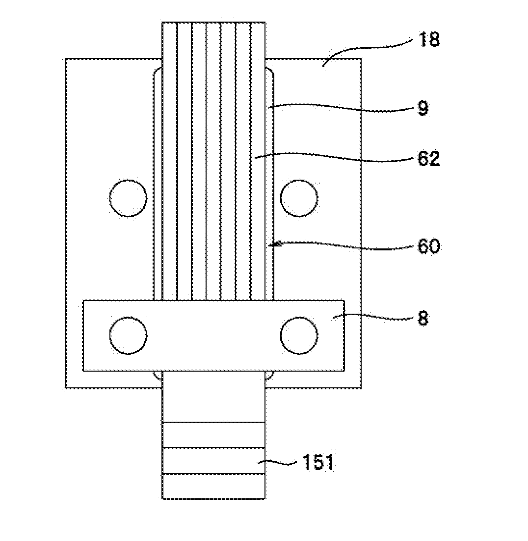
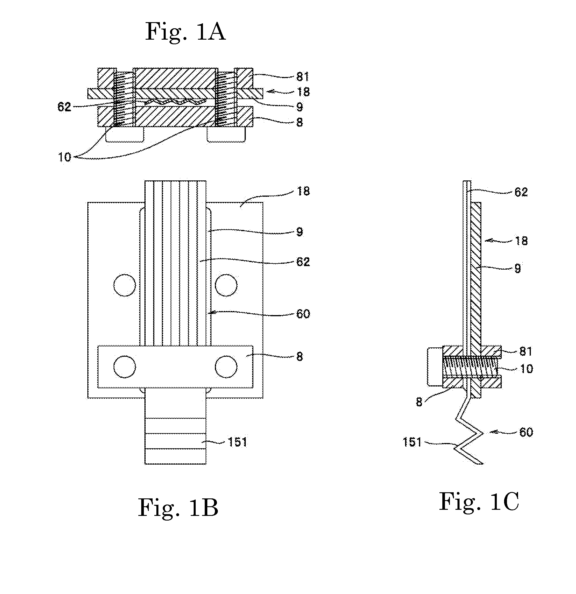
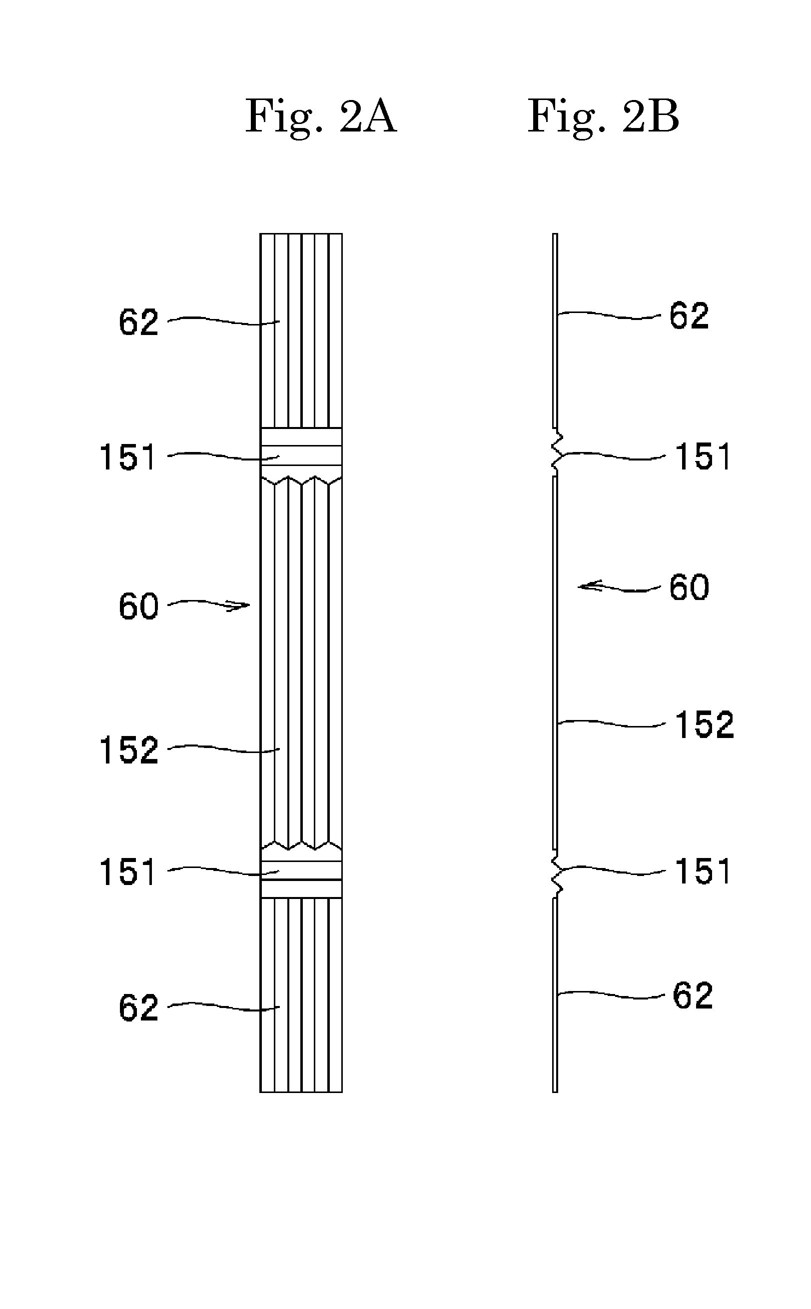
[0029]An embodiment of a ribbon microphone unit according to the present invention will be described with reference to the accompanying drawings. FIGS. 4A and 4B show an embodiment of the ribbon microphone unit according to the present invention. The ribbon microphone unit shown in FIG. 4A comprises a frame 7, a magnet 4, an electrode lead portion 18, a terminal strip 9, a tightening member comprising a pressure plate 8 and a support plate 81, a screw 10, and a ribbon diaphragm 60. The frame 7 is formed in a rectangular frame shape that is long in the longitudinal direction, and a screw hole for securing to the microphone case 1 is formed at four corners. On the inner surface of the frame 7, a pair of permanent magnets 4, 4 is fixed on both sides along the longitudinal direction, with a predetermined spacing between the both permanent magnets 4, 4. The frame 7 is made of a magnetic material, functions as a yoke, and constitutes a magnetic circuit that goes out of the permanent magne...


PUM


Abstract

A ribbon microphone unit includes: an electrode lead portion for conducting an electric signal which a ribbon diaphragm generates cooperating with a magnet; a tightening member for securing the ribbon diaphragm; and a screw for crimping the tightening member, wherein the tightening member is crimped via the ribbon diaphragm and the electrode lead portion by the screw, and wherein the ribbon diaphragm includes a portion sandwiched by the tightening member, and the portion is formed in an irregular shape in the thickness direction.

Description

BACKGROUND OF THE INVENTION[0001]1. Field of the Invention[0002]The present invention relates to ribbon microphones and ribbon microphone units.[0003]2. Related Background of the Invention[0004]A ribbon microphone includes a magnet for forming a magnetic field and a ribbon diaphragm, as the main component members. The magnet is disposed on both sides of the ribbon diaphragm to sandwich the same, whereby a magnetic field is formed between the magnets on the both sides. The ribbon diaphragm is given an appropriate tension and disposed within the magnetic field while the both longitudinal ends are held down. In response to a sound wave, the ribbon diaphragm vibrates within the magnetic field and thereby a current corresponding to the sound wave flows through the ribbon diaphragm and thus the sound wave is converted into an electric signal. Typically, an aluminum foil is used as the material of the ribbon diaphragm. Since aluminium has a small conductive resistance as compared with othe...

Claims


Application Information

Patent Timeline
Patent Type & Authority Applications(United States)
IPC IPC(8): H04R25/00
CPCH04R9/08H04R9/048
Inventor AKINO, HIROSHI
Owner AUDIO-TECHNICA
Why Eureka
Try Eureka