Seals in steam turbine

a technology of sealing structure and steam turbine, which is applied in the direction of liquid fuel engines, machines/engines, mechanical equipment, etc., can solve the problems of increasing the temperature of the contact part of the rotating portion, and the temperature of the rotating portion is not uniform, so as to suppress the increase in the temperature of the rotating portion

Inactive Publication Date: 2009-06-04
MITSUBISHI HITACHIPOWER SYST LTD
View PDF9 Cites 27 Cited by
  • Summary
  • Abstract
  • Description
  • Claims
  • Application Information

AI Technical Summary

Benefits of technology

[0013]The present invention can provide the seal structure for a steam turbine, which is capable of suppressing an increas

Problems solved by technology

Frictional heat generated by the contacts may increase the temperature of a contact part of the rotating portion.
When the contact part of the rotation portion increases in temperature due to the frictional heat,

Method used


Image

  • Seals in steam turbine
  • Seals in steam turbine
  • Seals in steam turbine

Examples


Embodiment Construction

[0023]An embodiment of the present invention will be described below with reference to the accompanying drawings.

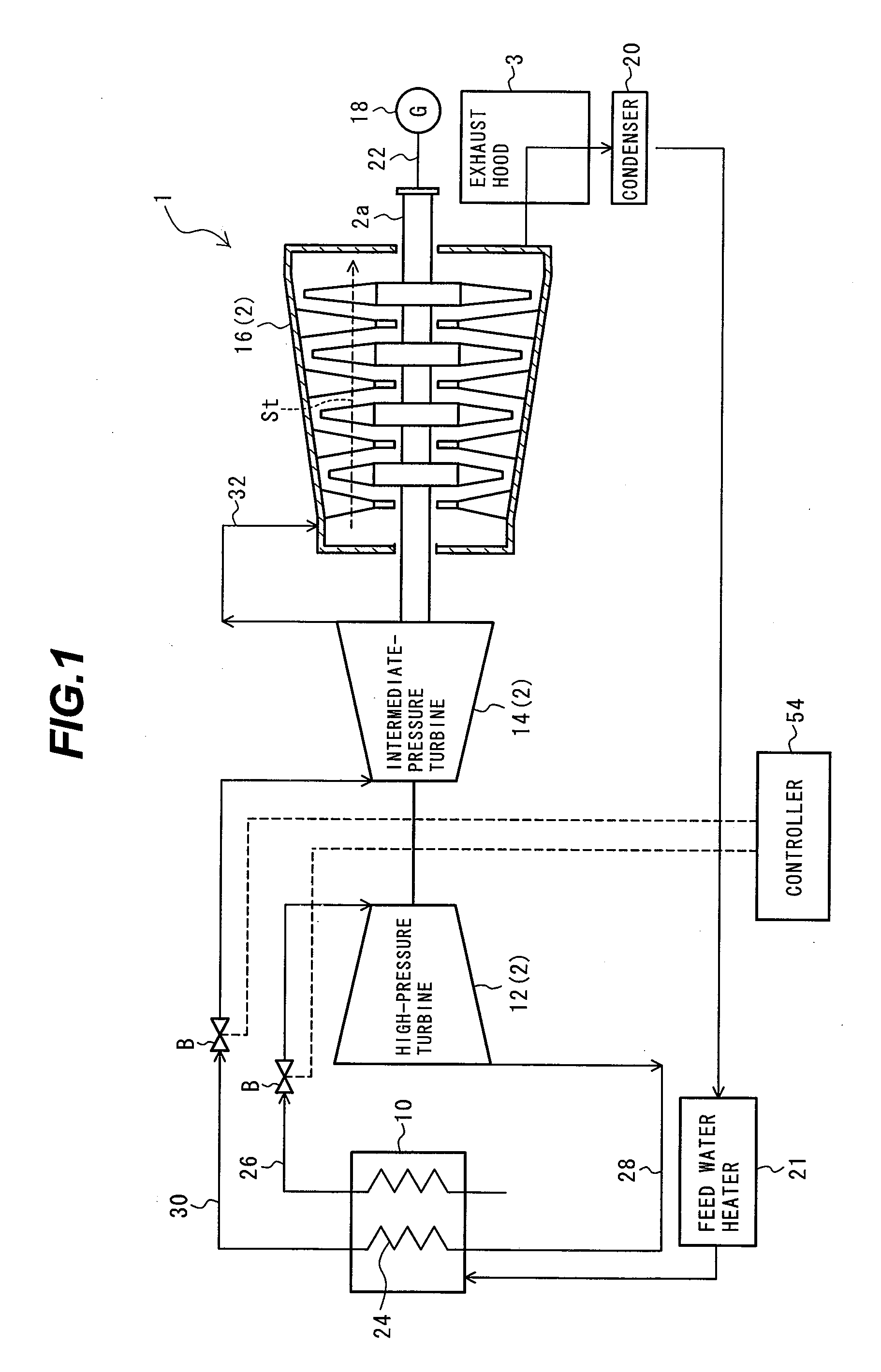
[0024]FIG. 1 is a systematic diagram showing a power plant having a steam turbine according to the present embodiment. As shown in FIG. 1, the power plant 1 includes a boiler 10, a steam turbine 2 (a high-pressure turbine 12, an intermediate-pressure turbine 14, and a low-pressure turbine 16), a generator 18 and a condenser 20. A rotor 2a of the low-pressure turbine 16 is connected to a drive shaft 22 of the generator 18. The generator 18 is driven by rotation of the low-pressure turbine 16 to generate electricity.

[0025]The boiler 10 is a steam generator and has a reheater 24 therein. The boiler 10 is connected to an inlet side of the high-pressure turbine 12 through a tube 26. An outlet side of the high-pressure turbine 12 is connected to the reheater 24 of the boiler 10 through a tube 28. The reheater 24 is connected to an inlet side of the intermediate-pressure turbine...


PUM


Abstract

A seal structure for a steam turbine is provided, which is capable of suppressing transfer of heat generated by a friction between a rotating portion and a fixed portion to the rotating portion and of suppressing an increase in the temperature of the rotating portion. A labyrinth seal device serves to suppress the amount of steam leaking from a clearance present between each stator blade (fixed portion) of the steam turbine and a rotor (rotating portion). The seal structure for the steam turbine is formed to ensure that permeable spacers made of a permeable metal are provided on the rotor and a seal stationary body and face respective seal fins provided in the labyrinth seal device.

Description

BACKGROUND OF THE INVENTION[0001]1. Field of the Invention[0002]The present invention relates to a seal structure for a steam turbine.[0003]2. Description of the Related Art[0004]A power plant generates electricity by rotating a turbine (steam turbine) by steam which a steam generator such as a boiler generates. As steam turbines used in such a power plant, a high-pressure turbine, an intermediate-pressure turbine and a low-pressure turbine are provided in the order from the upstream side of flow of the steam. The steam used for rotating the low-pressure turbine is introduced into a condenser through an exhaust hood. The steam is then condensed by the condenser and turned into water. The water is returned to the steam generator.[0005]In the steam turbine constituting a part of the power plant, each of stator blades fixed to the inner side of a casing is arranged between rotor blades that rotate with a rotor. The rotor blade and the stator blade form a stage.[0006]The steam introduce...

Claims


Application Information

Patent Timeline
IPC IPC(8): F01D11/08
CPCF01D11/001F01D11/02F01D11/08F16J15/162F05D2300/5024F16J15/4472F05D2220/31F05D2250/182F16J15/445
Inventor NARITA, KENJIROYAMAZAKI, HARUYUKIDOI, HIROYUKIKOBAYASHI, KEITORIYA, HAJIME
Owner MITSUBISHI HITACHIPOWER SYST LTD
Why Eureka
Try Eureka