Quick lift zero flutter oil service pump valve

a technology of oil service pump and valve opening, which is applied in the direction of positive displacement liquid engine, liquid fuel engine, borehole/well accessories, etc., can solve the problems of harsh conditions for pumps in oil field operations, and achieve the effect of preventing flutter, increasing force, and rapid opening of the valv

Inactive Publication Date: 2009-06-04
HALLIBURTON ENERGY SERVICES INC
View PDF3 Cites 16 Cited by
  • Summary
  • Abstract
  • Description
  • Claims
  • Application Information

AI Technical Summary

Benefits of technology

[0006]Disclosed herein is a suction valve for a positive displacement pump. At least two springs are used as an actuator for a valve plug. A first spring has an uncompressed length selected so that it is compressed when the valve is closed, thereby providing a preload force urging the valve toward a closed position when the valve is closed and increasing force as the valve opens. A second spring has an uncompressed length selected so that the second spring is not compressed until after a preselected valve plug lift. The first spring is relatively light, as compared to the prior art, and permits rapid opening of the valve to avoid cavitation. The second spring increases the effective spring constant when the valve is open to prevent flutter and to assist in closing of the valve upon commencement of a discharge pump stroke.

Problems solved by technology

Pumps in oil field operations often endure harsh conditions, especially when pumping abrasive fluids (such as fracturing fluids).

Method used


Image

  • Quick lift zero flutter oil service pump valve
  • Quick lift zero flutter oil service pump valve
  • Quick lift zero flutter oil service pump valve

Examples


Embodiment Construction

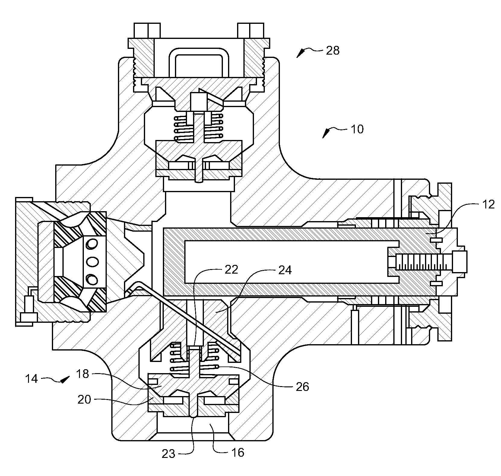
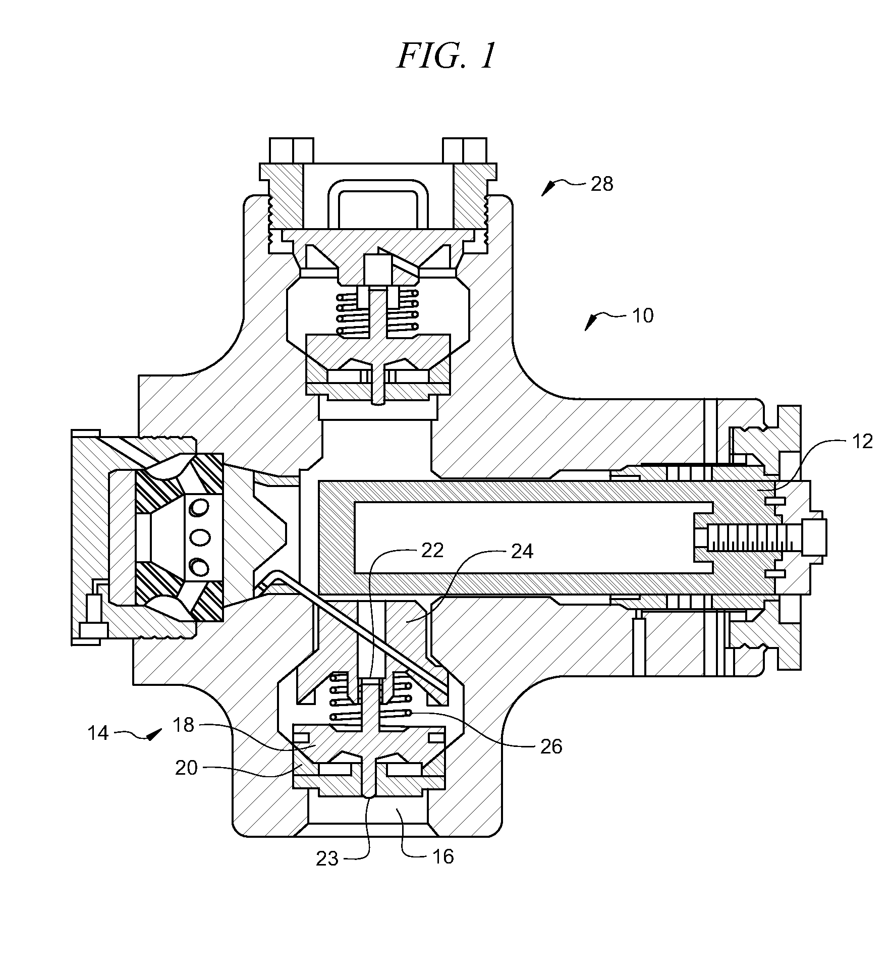
[0010]FIG. 1 is an illustration of a cylinder 10 of a positive displacement pump which may incorporate a multiple spring valve system as disclosed herein. The cylinder includes a piston 12 which is moved in and out of the cylinder 10 to alternately produce discharge pressure and suction pressure in the cylinder 10. The piston 12 is driven by a prime mover such as a motor as well known in the art. A suction valve 14 is provided between the cylinder 10 and a suction inlet 16. The inlet 16 is connected to a source of fluid such as a well treating fluid, e.g. fracturing fluid. The suction valve 14 includes a moving valve plug 18 and a valve seat 20. The valve plug 18 includes a stem 22 which may move within a guideway in a spring retainer 24. In this embodiment, the valve plug 18 also has a second valve stem 23 which may move within a guideway below the valve seat 20. A valve actuator, in this case a spring 26, is provided around stem 22 and between the spring retainer 24 and the valve ...


PUM


Abstract

A suction valve for a positive displacement pump. Two springs are used to actuate a valve plug. A first spring has an uncompressed length greater than a distance between a spring retainer and the valve plug, providing a preload force closing the valve. A second spring has an uncompressed length less than the distance between the retainer and the plug, providing closing force to the plug only after a preselected valve lift. The first spring is relatively light and permits rapid opening of the valve to avoid cavitation. The second spring increases the effective spring constant when the valve is open to prevent flutter and to assist in closing of the valve upon commencement of a discharge pump stroke.

Description

CROSS-REFERENCE TO RELATED APPLICATIONS[0001]None.STATEMENT REGARDING FEDERALLY SPONSORED RESEARCH OR DEVELOPMENT[0002]Not applicable.REFERENCE TO A MICROFICHE APPENDIX[0003]Not applicable.FIELD OF THE INVENTION[0004]Embodiments described herein relate to positive displacement pumps, and more specifically to devices and methods to improve the efficiency, durability, performance, and operating characteristics of reciprocating positive displacement pumps (of the sort that might be used in pumping wellbore servicing fluids) by using a multiple, e.g. two, spring system for operating suction valve(s) of the pump.BACKGROUND OF THE INVENTION[0005]Positive displacement pumps, and specifically reciprocating pumps, are used in all phases of oilfield operation to pump water, cement, fracturing fluids, and other stimulation or servicing fluids. Pumps in oil field operations often endure harsh conditions, especially when pumping abrasive fluids (such as fracturing fluids). Thus, there is an ongo...

Claims


Application Information

Patent Timeline
Patent Type & Authority Applications(United States)
IPC IPC(8): F04B53/10E21B34/16F16K15/06F04B39/10
CPCE21B34/16F04B53/10F04B39/10E21B43/12Y10T137/7932
Inventor BLANCO, IVAN
Owner HALLIBURTON ENERGY SERVICES INC
Why Eureka
Try Eureka