
Hydraulic Drive Device for Dump Truck

a technology of hydraulic drive and dump truck, which is applied in the direction of electric devices, machines/engines, transportation items, etc., can solve the problems of wasteful consumption of energy and transmission of engine noise, and achieve the effects of reducing engine noise to the surrounding environment, preventing an excessive increase in engine rotation speed, and saving energy

Inactive Publication Date: 2009-06-11
NIHON KENKI CO LTD
View PDF1 Cites 10 Cited by
  • Summary
  • Abstract
  • Description
  • Claims
  • Application Information

AI Technical Summary

Benefits of technology

[0013]The present invention can prevent an excessive increase in engine rotation speed upon operation of a truck body, thereby making it possible to reduce engine noise to the surrounding environment and also to realize energy saving. Accordingly, the present invention can provide a high-reliability dump truck.

Problems solved by technology

If the rotation speed of the engine is increased too much, however, engine noise is transmitted to the environment surrounding the work site, and moreover, energy is wastefully consumed.

Method used


Image

  • Hydraulic Drive Device for Dump Truck
  • Hydraulic Drive Device for Dump Truck
  • Hydraulic Drive Device for Dump Truck

Examples


Embodiment Construction

[0014]The best mode for carrying out the hydraulic drive system according to the present invention for a dump truck will hereinafter be described with reference to the drawings.

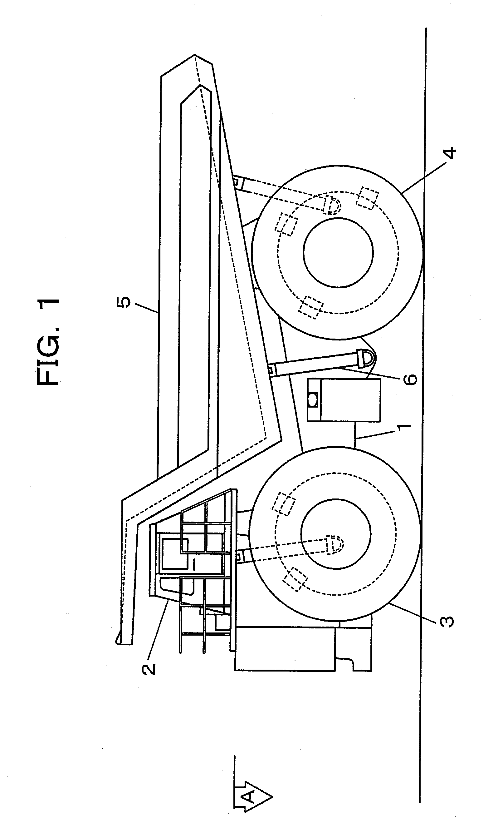
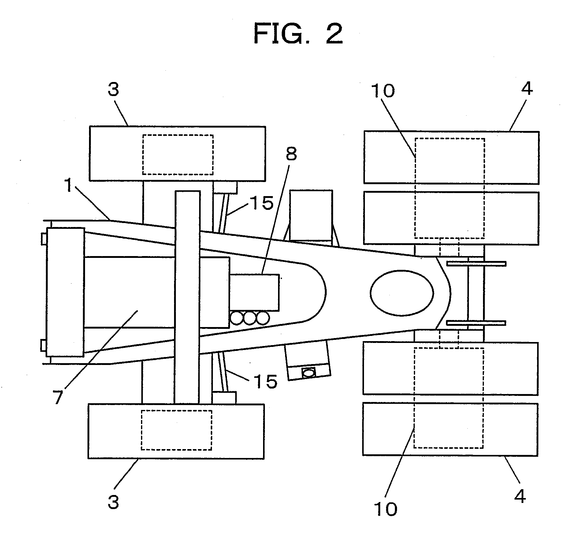
[0015]FIG. 1 is a side view of one example of a dump truck on which one embodiment of the hydraulic drive system according to the present invention can be mounted, and FIG. 2 is a view taken in the direction of arrow A of FIG. 1.

[0016]As illustrated in FIG. 1, the dump truck on which the one embodiment of the hydraulic drive system according to the present invention can be mounted is provided with a truck frame 1 forming an undercarriage, a cab 2 arranged on the truck frame 1 at a forward position thereof, front wheels 3 and rear wheels 4, a truck body 5 pivotable in an up-and-down direction about a pivotal fulcrum set on a rear part of the truck frame 1, and a pair of left and right truck-body elevating cylinders 6 for pivoting the truck body 5 in the up-and-down direction. As depicted in FIG. 2, the dump tr...


PUM


Abstract

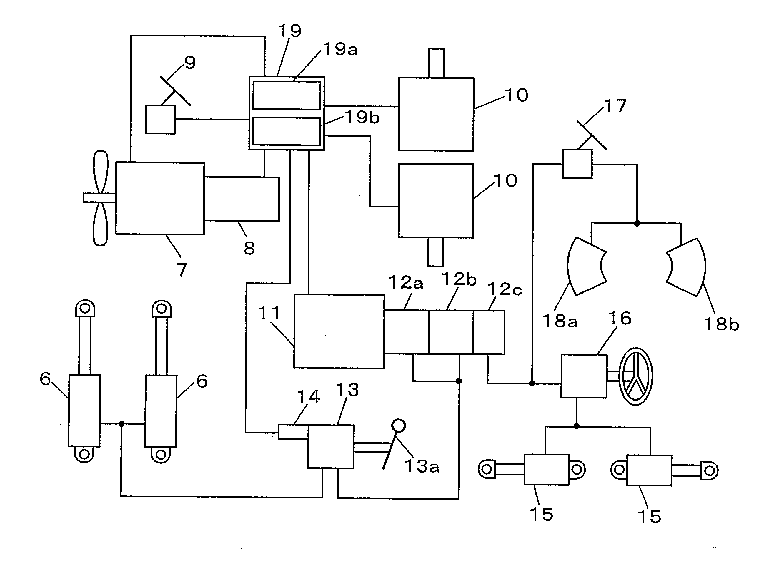
[OBJECT] To provide a hydraulic drive system for a dump truck, which can prevent an excessive increase in engine rotation speed upon operation of a truck body.[MEANS FOR ACHIEVING THE OBJECT] A hydraulic drive system is provided with a generator 8 for outputting electricity corresponding to a rotation speed of an engine 7, an electric motor 11 drivable responsive to the electricity from the generator 8, hydraulic pumps 12a, 12b drivable by the electric motor 11, truck-body elevating cylinders 6 for pivoting a truck body 5 in an up-and-down direction, and a stroke detector 14 for detecting a stroke of the control apparatus of the truck-body elevating cylinders 6, and is also provided with a controller 19 for performing control of engine rotation speed. The controller 19 includes a motor electric-power computing means 19a for determining electric power for the electric motor 11, which corresponds to the stroke detected by the stroke detector 14, and a discrimination means 19b for discriminating whether or not the electricity from the generator 8 has become greater than the thus-determined electric power for the electric motor 1.

Description

TECHNICAL FIELD[0001]This invention relates to a hydraulic drive system for a dump truck used in a mine, which is provided with an electric motor for driving a hydraulic pump such that pressure oil is delivered to actuate truck-body elevating cylinders.BACKGROUND ART[0002]As a conventional technology involving an electric motor for driving a hydraulic pump, one disclosed in Patent Document 1 can be mentioned. Although this conventional technology is applied to a hydraulic excavator rather than a dump truck to which the present invention is applied, it is provided with an engine, a generator for outputting electricity corresponding to a rotation speed of the engine, an electric motor to which the electricity is fed from the generator via an inverter, a hydraulic pump drivable by the electric motor, hydraulic actuators operable by pressure oil delivered from the hydraulic pump, and control valves for controlling flows of pressure oil to be fed from the hydraulic pump to the hydraulic ...

Claims


Application Information

Patent Timeline
Patent Type & Authority Applications(United States)
IPC IPC(8): F15B11/02B60P1/16F15B9/00B60K6/46B60W10/30B60W20/00F02D29/06F15B11/00
CPCB60K6/46Y02T10/70B60L11/08B60L2220/44B60L2260/28B60P1/162B60W10/08B60W10/30B60W20/00B60W2710/0644B60Y2200/14B65F3/00F02D29/04F02D29/06F16H61/475Y02T10/6217Y02T10/7077B60K25/00Y02W30/10B60L50/13Y02T10/62Y02T10/7072B60W10/06B60W2300/12
Inventor YASUDA, TOMOHIKOYAGYU, TAKASHITANAKA, YASUOFUSHIKI, MICHIOKANEKO, SATORU
Owner NIHON KENKI CO LTD
Learn More