Power transmission system for an aircraft

a transmission system and aircraft technology, applied in the field of aircraft power transmission system, can solve the problems of time-consuming and costing money, and achieve the effects of reducing time and cost, facilitating assembling/disassembling the aircraft, and simplifying the transmission mechanism

Inactive Publication Date: 2009-06-11
THUNDER TIGER
View PDF12 Cites 6 Cited by
  • Summary
  • Abstract
  • Description
  • Claims
  • Application Information

AI Technical Summary

Benefits of technology

[0006]An objective of the invention is to provide a power transmission system for an aircraft that solves the above-mentioned problems. It uses a simp

Problems solved by technology

It is time-consumi

Method used


Image

  • Power transmission system for an aircraft
  • Power transmission system for an aircraft
  • Power transmission system for an aircraft

Examples


Embodiment Construction

[0011]The present invention will be apparent from the following detailed description, which proceeds with reference to the accompanying drawings, wherein the same references relate to the same elements.

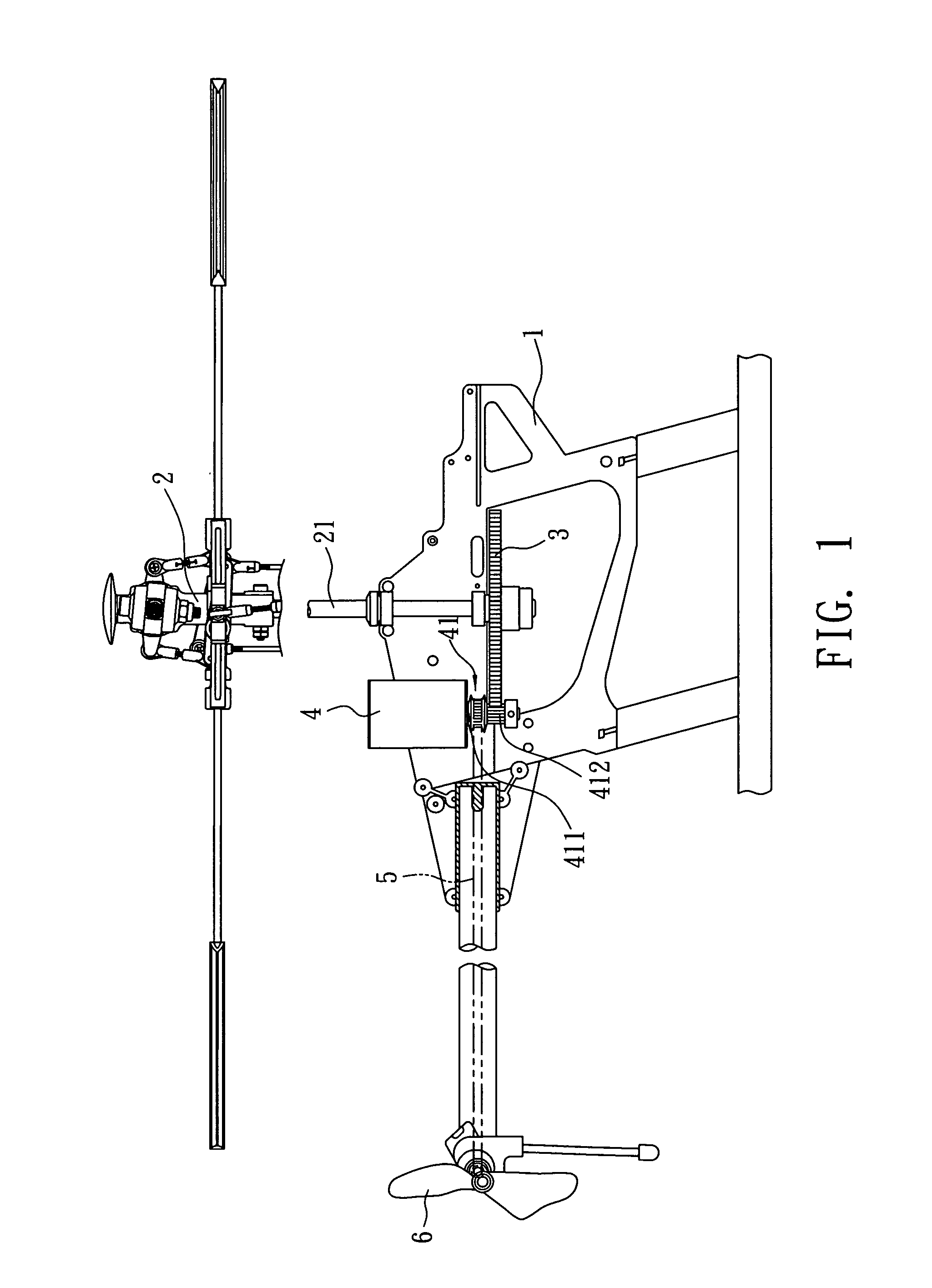
[0012]Please refer to FIG. 1 for an embodiment of the invention. The structure disclosed in this particular embodiment is only an example and should not be used to restrict the invention defined by the claims.

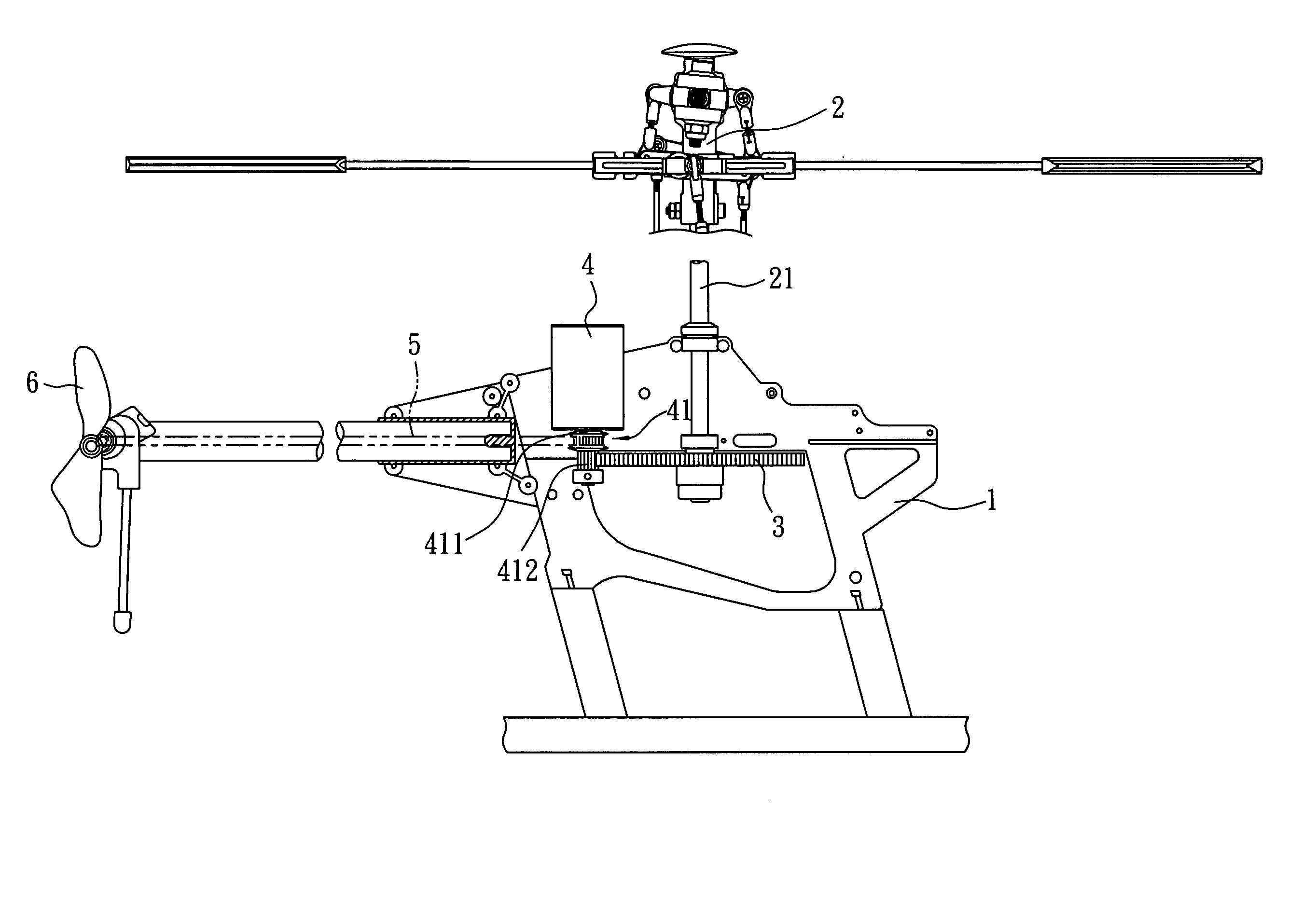
[0013]This embodiment provides a power transmission system for an aircraft. The aircraft herein refers to a rotorcraft. It has a body 1 for fixing various components. A rotor 2 is provided above the body 1. A vertical rotating axle 21 is pivotally connected to the front end of the body 1 using its one end. The rotating axle 21 is connected with a gear disk 3 in the vicinity of the body 1 for transverse transmission.

[0014]A driving motor 4 is fixed between the rotating axle 21 and the tail inside the body 1. The driving motor 4 has a driving axle 41 pivotal along the bottom direct...


PUM


Abstract

A power transmission system for an aircraft is disclosed. A driving motor having a driving axle is provided inside an aircraft. The driving axle has a gear part and a wheel part. They drive a gear disk and a belt, respectively, to rotate the rotor and the tail rotor. The invention simplifies the power transmission structure of the aircraft.

Description

BACKGROUND OF THE INVENTION[0001]1. Field of Invention[0002]The invention relates to a power transmission system for an aircraft and, in particular, to a power transmission system that uses a simple mechanism to rotate the rotor and tail rotor of the aircraft.[0003]2. Related Art[0004]As shown in FIG. 2, an aircraft 9 has a rotor 92 above its body 91 and a tail rotor 93 pivotally installed at its tail. The rotor 92 is pivotally connected to the body 91 via a rotating axis 921. The body 91 is provided with a driving motor 94 with a tooth-like driving axle 941 for driving a first gear disk 95 coaxially disposed with the rotor 92. The first gear disk 95 matches with the driving axle 941 and rotates the rotor 92. A second gear disk 96 is coaxially disposed with the first gear disk 95 inside the body 91 to rotate a driven gear 97. The driven gear 97 drives a transmission belt 98 whose other end is connected to rotate the tail rotor 93.[0005]To take apart or assemble the above-mentioned t...

Claims


Application Information

Patent Timeline
IPC IPC(8): B64C27/12
CPCA63H27/12
Inventor TAYA, SHIGETADA
Owner THUNDER TIGER
Why Eureka
Try Eureka