

Rotation angle sensor and scissors gear suitable therefor
a technology of rotation angle sensor and scissors, which is applied in the direction of instruments, mechanical equipment, and gear, can solve the problems of sensor deterioration, increased manufacturing cost, and sensor disclosed in this literature, and achieve the effect of preventing deterioration in detection accuracy
- Summary
- Abstract
- Description
- Claims
- Application Information
AI Technical Summary
Benefits of technology
Problems solved by technology
Method used
Image

Examples
first embodiment
(Configuration)
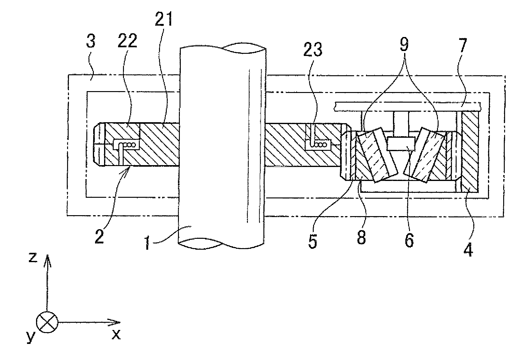
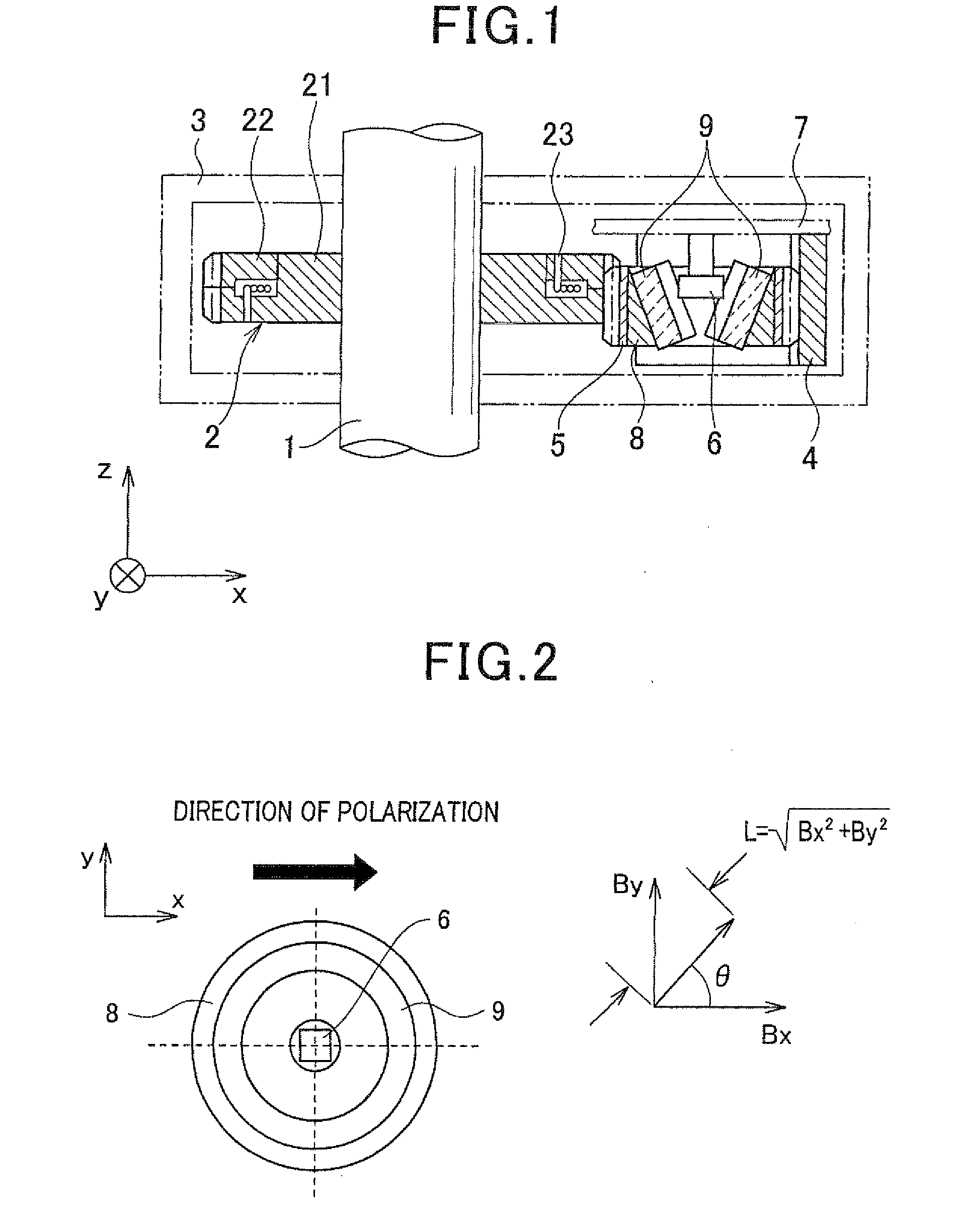
[0073]Referring to FIG. 1, hereinafter is described a steering angle sensor according to a first embodiment. FIG. 1 is a schematic cross-sectional view illustrating the sensor, and FIG. 2 is a plane view illustrating a principal part of the sensor.
[0074]The steering angle sensor is a sensor for detecting an angle of rotation of a rotating body 1 that configures a steering shaft. The rotating body 1 is fixed with a driving gear 2 serving a scissors gear. The rotating body 1 is disposed passing through a housing 3.
[0075]A screw receiver 4 is fixed to an area of an inner peripheral surface of the housing 3. A driven gear 5 is disposed being engaged with the driving gear 2 and the screw receiver 4. A magnetic sensing element 6 is disposed being vertically hung from the housing 3 toward an axis of the driven gear 5.
[0076]The sensor also includes a circuit board 7 on which an electronic circuit, i.e. a signal processing unit (not shown), of the present invention is mounted....
second embodiment
[0124]Hereinafter is described a second embodiment of the present invention referring to FIG. 9. In the present and the subsequent embodiments, the identical or similar components to those in the first embodiment described above are given the same reference numerals for the sake of omitting explanation.
[0125]The present embodiment is different from the first embodiment shown in FIG. 1 in that the driving gear 2 is configured by a simple single gear and that a leaf spring member 10 is interposed between the bottom surface, or the outer peripheral portion, of the screw receiver 4 and the inner peripheral surface of the housing 3, so that the screw receiver 4 can be elastically biased to the side of the rotating body 1 via the driven gear 5.
[0126]In this case as well, the driven gear 5 should be held by the housing 3 in a manner of enabling displacement in the radial direction of the rotating body 1.
[0127]With this configuration, the leaf spring member 10 serving as an elastic biasing ...
third embodiment
[0129]With reference to FIGS. 10A to 11B, hereinafter is described a third embodiment of the present invention.
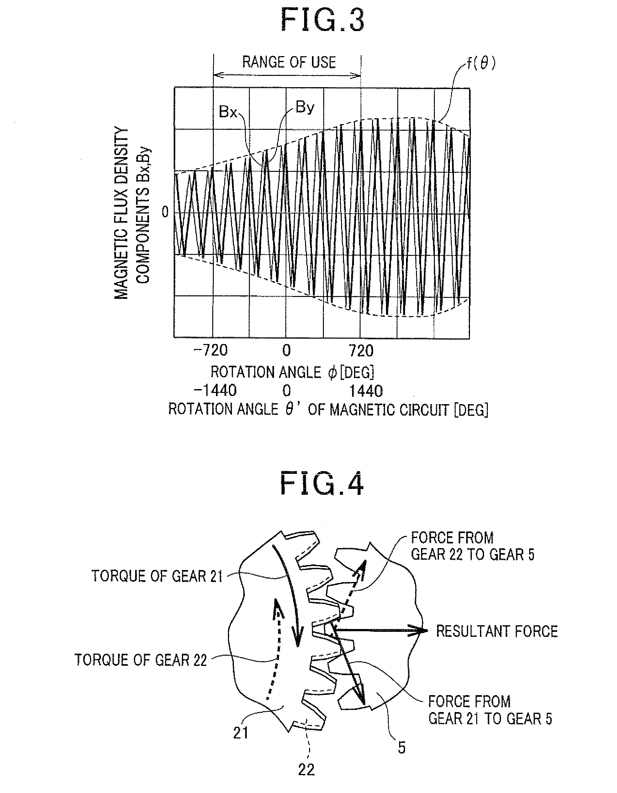
[0130]The present embodiment is different from the first embodiment shown in FIG. 1 in that the shape has been changed in each of the first and second gears 21 and 22 that configure the scissors gear, i.e. the driving gear 2.
[0131]Referring to FIGS. 10A to 11B, the driving gear 2 of the present embodiment is described in detail. FIG. 10A is a plane view illustrating the driving gear 2 and FIG. 10B is an axial cross-sectional view of the driving gear 2.
[0132]FIG. 11A is an axially cross-sectional view illustrating only the first gear 21, and FIG. 11B illustrates the first gear 21 as viewed from the direction indicated by an arrow “A” in FIG. 11A.
[0133]The driving gear 2 includes the first gear 21, the second gear 22 which is axially adjacent to the first gear 21, and the coil spring 23. The first and second gears 21 and 22 are axially fitted to each other to configure the dr...
PUM
 Abstract
Description
Claims
Application Information