Wirelessly communicating remote devices over a
wide area is challenging due to technological, logistical, economical, environmental and regulative factors.
The deployment and maintenance of thousands and even millions of devices, spread in large cities or entire country, take much time and efforts.
Also, since RF spectrum is limited, nearby systems can introduce interference.
Physically accessing and reading these meters can be a complex,
time consuming and costly task.
Due to small dimensions of meter and radio, sometimes obscured location, battery limitations and regulative transmission power restrictions, communications range is typically limited.
In the absence on any further radio network, this method requires the meter to be polled on a regular basis by an interrogator, either portable or vehicular, typically necessary to get in close proximity to the meters, therefore still travel intensively.
Yet, those mAMR methods known also as drive-by or walk-by AMR, are not
fully automated, require dedicated reading staff and establishing a direct link between the reader and every meter radio, thus require much reading efforts, sensitive to human costs and faults.
However, such networks are expensive to deploy and to maintain, usually require dedicated real estate, frequencies, and often are in continuous conflict with environmental protectors and regulators.
AMR over public networks, on the other hand, is subject to restricted
quality of service, operational fees, expensive transmitters, etc.
Yet, though AMR based on public
radio networks saves installation and maintenance costs, it might be subject to operational fees and usually requires relatively expensive meter radios.
Thus, this approach is not straight forward.
Power lines obtain a very good
network topology for AMR however present quite a hostile communications environment, due to
noise, sensitivity of electrical appliances (TV and radio tuners) and restricting regulations.
A cost effective radio network dedicated for AMR is challenging due to technology barriers and strict regulations that require solutions not always justified for a niche application.
For example, regulation limits the transmission power of a radio, bounding its communications range, consequently requiring additional base stations to
relay meter's data to a central
station.
Another regulatory restriction is concerned with RF spectrum, limiting the usage of frequency bandwidth, often requiring AMR networks to share spectrum with other applications operating in the same area.
Still, dedicated fixed
radio networks for AMR are not always cost effective and dedicated network installation and operation costs are not easily justified, business wise.
Ad-hoc or
wireless mesh networks often present a challenge to define the best
route to communicate between a source node and a destination node.
The cost is the cost associated with communication with the destination.
The low traffic nature of AMR usually suits the mesh concept; however in many cases mesh cannot provide a full proof solution for AMR.
Mesh networks could efficiently
route meter records among a group of nearby meters, e.g. in same building, however due to the low power nature of meter radios, this concept will not easily deal with large gaps between meters, or groups of meters, as introduced by large non residential buildings and yards, parks and gardens, lakes and rivers, wide highways,
train and
bus stations, parking lots, etc.
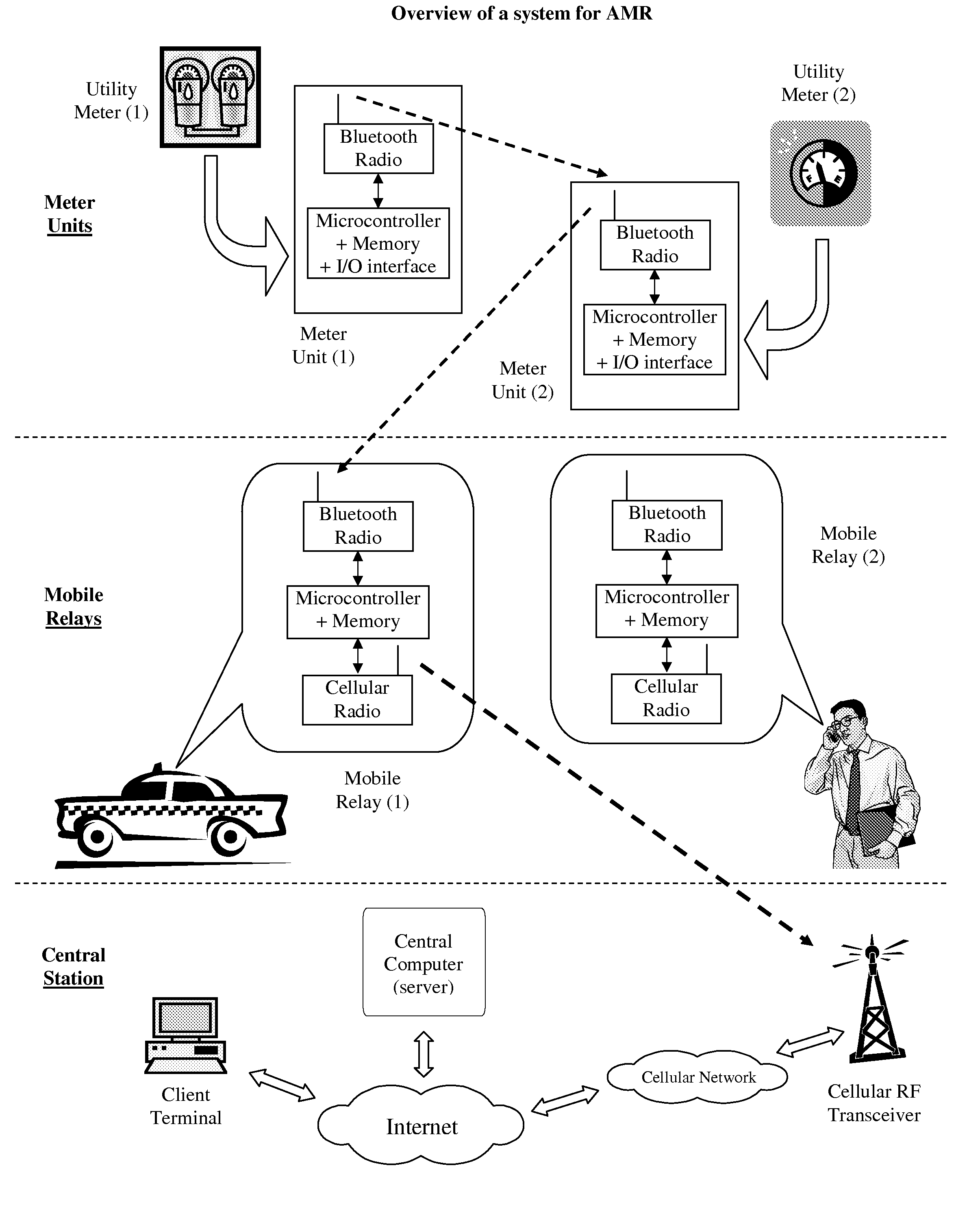
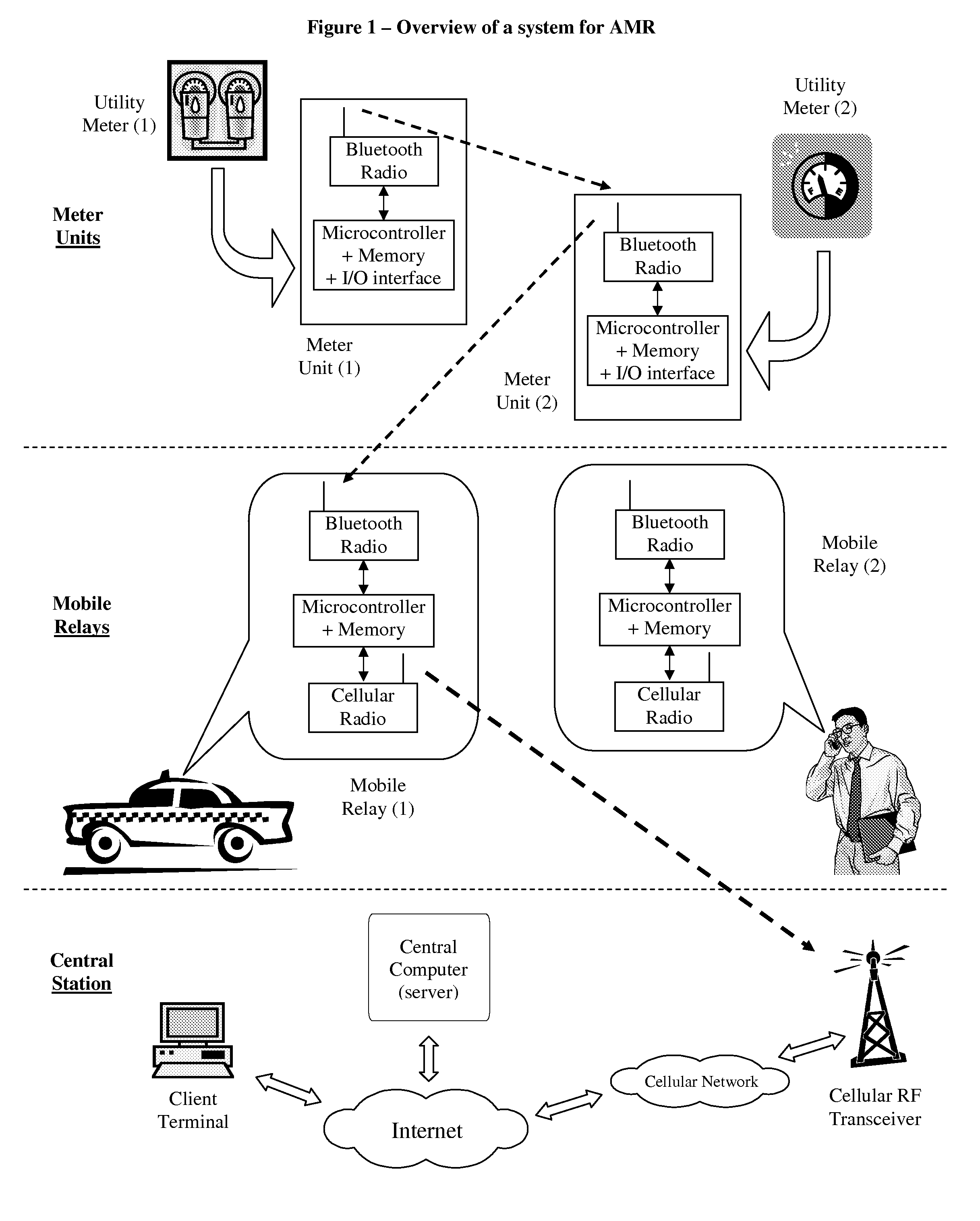
However, when mobile relays are deployed and roam randomly or semi-randomly, i.e. do not travel systematically to get closer to meters, as Israeli patent 145737 teaches, it is difficult to ensure or predict a successful delivery of data from a meter to the central
station.
This drawback is particularly pertinent in dense urban areas, where meters may be installed in basements, high floors, or other locations far away or blocked (for communication purposes) from routes where the mobile relays might travel.
The present art methods described above have not yet provided satisfactory solutions to the problem of efficient and cost effective remote AMR.

