Apparatus and method for tracking an object

Inactive Publication Date: 2009-06-11
NEPTEC
View PDF16 Cites 140 Cited by
  • Summary
  • Abstract
  • Description
  • Claims
  • Application Information

AI Technical Summary

Benefits of technology

[0017]Advantageously, the use of two beams facilitates measuring the position of the target surface using two measurement devices which may use either the same or different measuring techniques. In one embodiment, one of the two beams is used to measure the position of the object using a triangulation technique and the other beam is used to measure the position of the target surface using another technique, for example, a time of flight technique.
[0018]In one embodiment, the first and second beams have a parameter whose value for the first beam is different to that of the second beam. For example, the two beams may have different wavelengths. This facilitates detection of the beams at the receiver side.
[0019]The provision of at least two beams also allows the beams to be controlled independently. For example, one beam could be pulsed and the other continuous. In another example, the beams may have different sizes. The beams may ha

Problems solved by technology

A drawback of these co-aligned optical systems is the requirement of a very large dynamic range.
Thus, these systems cannot be used to detect targets at very short range due to the saturation of the receiving detector.
Another drawback of these systems is the difficulty in detecting objects located in fog or mist or an atmosphere containing airborne particulate matter such as dust or sand.
Another drawback of the systems shown in FIGS. 1 and 2 is the effective attenuation of the rejected and reflected be

Method used


Image

  • Apparatus and method for tracking an object
  • Apparatus and method for tracking an object
  • Apparatus and method for tracking an object

Examples


Example

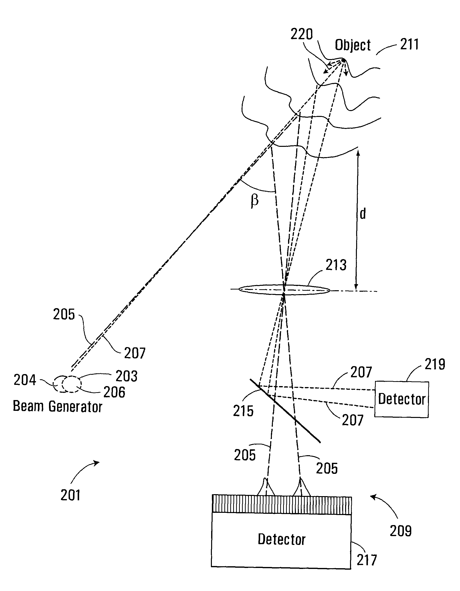
[0055]FIG. 6 shows an apparatus according to an embodiment of the present invention. The apparatus 201 comprises a beam generator 203 for generating first and second beams of energy 205, 207 and a receiving system 209 for receiving beam energy from the first and second beams reflected from an object 211 spaced from the apparatus. In this embodiment, the receiving system comprises a collection lens 213 for receiving beam energy scattered from the object and for imaging (e.g. focussing) the received beam energy, a beam separator 215 for spatially separating the first and second beams 205, 207 reflected from the object, and first and second detectors 217, 219 for detecting the first and second beams, respectively. It will be appreciated that for a diffuse surface, the incident beams will be scattered by the surface as shown by the ray lines 220, for example, and a portion of the scattered radiation will be received and imaged by the lens 213 (or other device). It is this portion of the...


PUM


Abstract

An apparatus for tracking an object or measuring the range of an object comprises a beam generator for generating first and second beams of energy and projecting the first and second beams towards a target surface whose distance from the apparatus is to be measured, a receiver for receiving energy from the first and second beams reflected from the target surface and for projecting beam energy reflected from the first beam onto a detector for detecting the position of the first beam energy. The position is dependent on the angle between the incident first beam and reflected first beam energy at the target surface, and thereby on the distance between the apparatus and the position from which the first beam is reflected from the surface. A second detector is provided for receiving second beam energy reflected from the target surface for measuring the range of the target by time of flight.

Description

FIELD OF THE INVENTION[0001]The present invention relates to apparatus and methods for tracking objects, and in particular but not limited to, apparatus and methods for measuring the distance to an object.BACKGROUND OF THE INVENTION[0002]Existing, optical-based systems for measuring the range of an object include LIDAR (light detection and ranging) systems in which a laser beam is projected onto an object and laser light reflected from the object is detected. Examples of LIDAR systems are shown in schematically in FIGS. 1 to 4.[0003]Referring to FIG. 1, the system 1 includes a laser source 3, a first lens 5, a beam splitter 7, an optical scanner 9, a second lens 11 and a detector 13. A projected pulsed laser beam 15 from the source 3 passes through the first lens 5 and beam splitter 7 to the optical scanner, which controls the beam direction to project the beam onto an object (not shown) whose range is to be measured. The optical scanner 9 also receives laser light reflected from th...

Claims


Application Information

Patent Timeline
IPC IPC(8): G01C3/00G01S17/87
CPCG01S7/285G01S7/4811G01S7/4812G01S17/87G01S13/48G01S13/87G01S17/08G01S7/4817
Inventor ZHU, XIANGSMITH, I. CHRISTINE
Owner NEPTEC
Why Eureka
Try Eureka