Developing Device, Developing Method, and Image Forming Apparatus

a technology of developing device and developing method, which is applied in the direction of electrographic process apparatus, instruments, optics, etc., can solve the problems of affecting the appearance quality of the image, so as to reduce the consumption of liquid developer, suppress the amount of liquid developer applied, and suppress the formation of the liquid ring

Inactive Publication Date: 2009-06-11
SEIKO EPSON CORP
View PDF8 Cites 10 Cited by
  • Summary
  • Abstract
  • Description
  • Claims
  • Application Information

AI Technical Summary

Benefits of technology

[0034]According to the aspects of the invention, it is possible to suppress the amount of liquid developer applied to both ends of the developing roller, thereby suppressing the formation of the liquid ring as much as possible. Accordingly, the inside of the apparatus is not contaminated by the drop of the liquid developer from the liquid ring, thereby reducing the consumption of the liquid developer.

Problems solved by technology

Accordingly, when the image forming apparatus is restarted, the image quality is deteriorated due to the line-shaped mark.
The line-shaped mark is different from the liquid ring and can be said to be a problem caused because the developer is liquid.
In the image forming apparatus described in JP-A-2000-235306, even when the problem with the liquid ring has been solved at the time of developing, there is a problem in that the liquid developer removed from the stepped roller portion 23b is saturated in a short time to form a liquid ring at the end of the stepped roller portion 23b.
When such a liquid ring is formed in the developing device or the image forming apparatus, the liquid developer gathered as the liquid ring during the deactivation of the device or apparatus is dropped to the lower portion of the device or apparatus, thereby causing contamination or trouble.
The toner component in the liquid ring is solidified during the deactivation of the device or apparatus to secure the roller and the blade with each other, thereby causing a problem with damage on the surface of the roller or the blade.

Method used


Image

  • Developing Device, Developing Method, and Image Forming Apparatus
  • Developing Device, Developing Method, and Image Forming Apparatus
  • Developing Device, Developing Method, and Image Forming Apparatus

Examples


Embodiment Construction

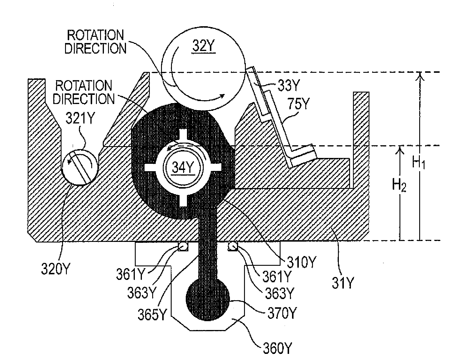
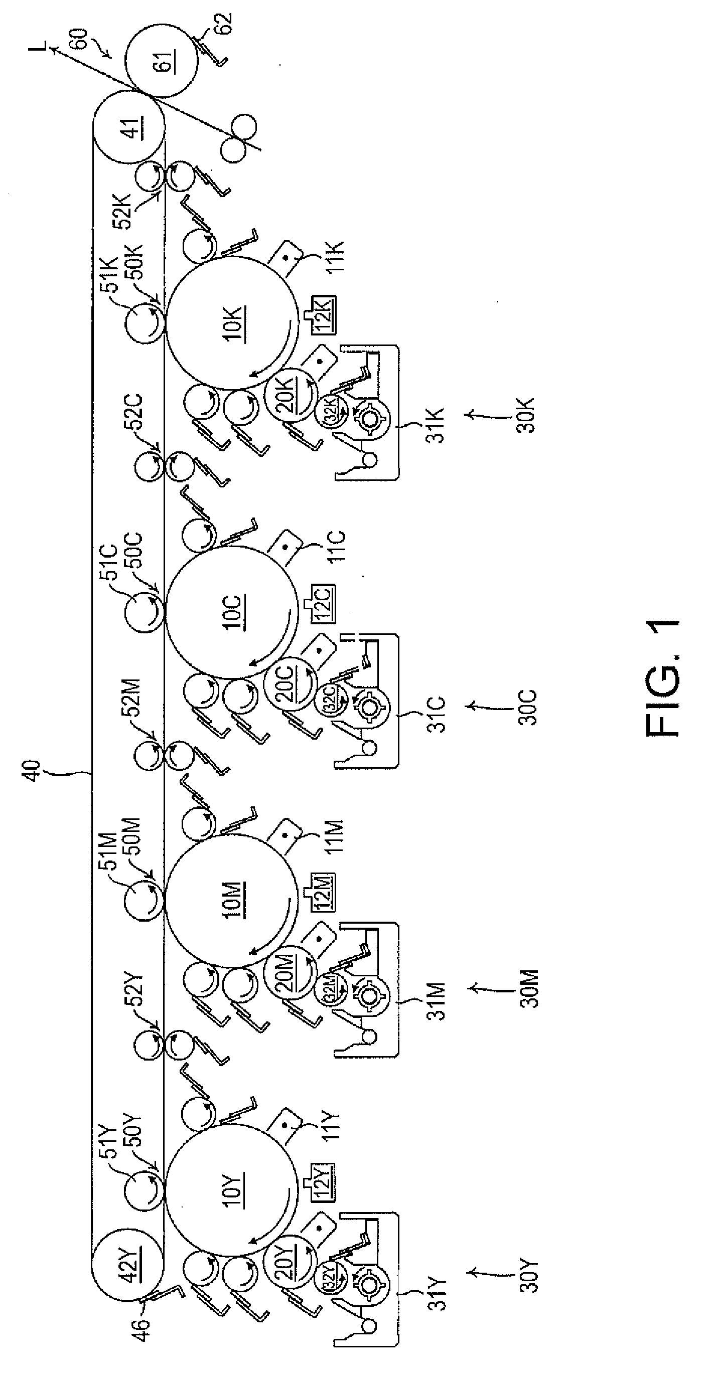
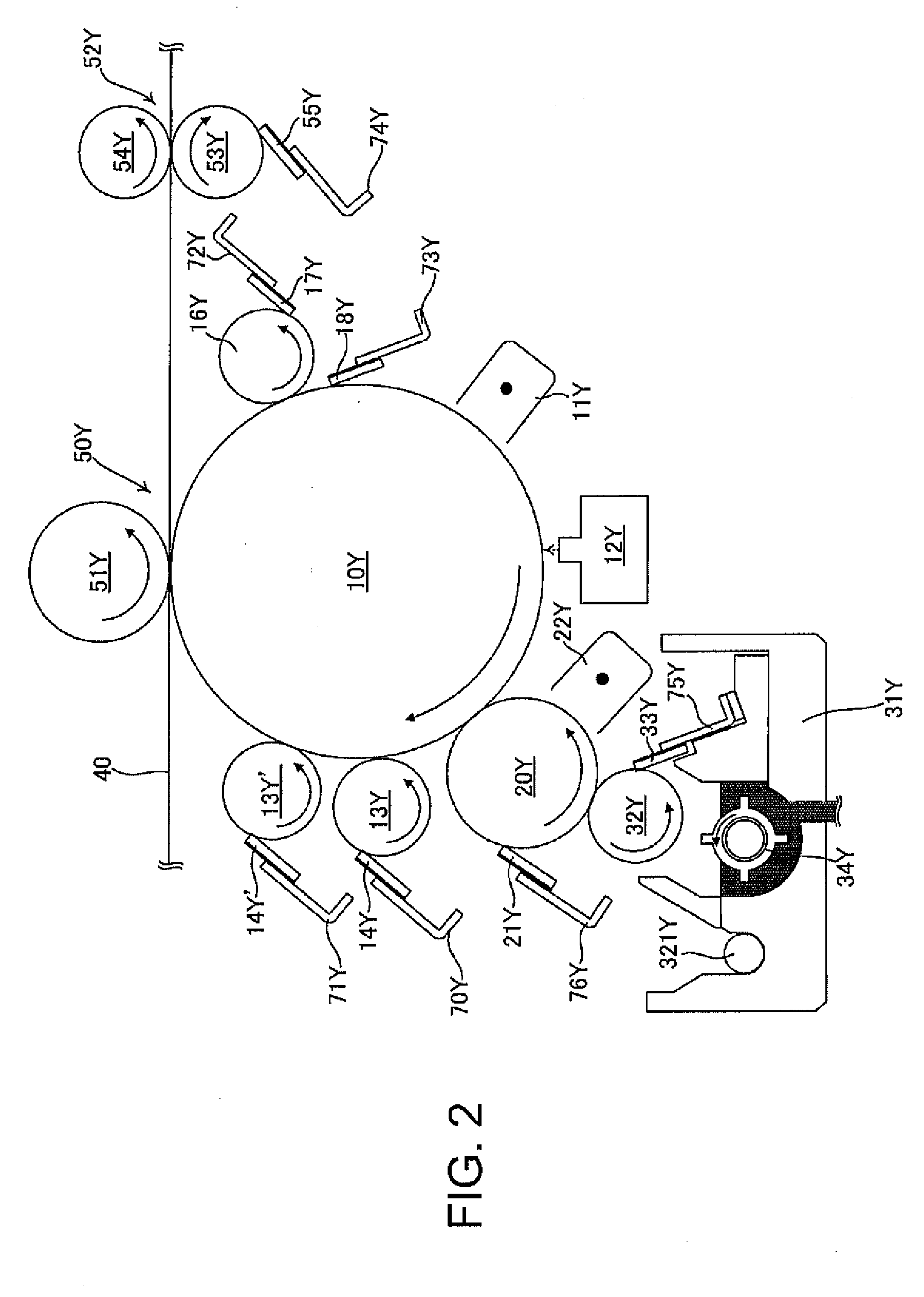
[0052]Hereinafter, embodiments of the invention will be described with reference to the accompanying drawings. FIG. 1 is a diagram illustrating primary elements of an image forming apparatus according to an embodiment of the invention. In image forming sections of respective colors disposed at the center of the image forming apparatus, developing devices 30Y, 30M, 30C, and 30K are disposed in the lower portion of the image forming apparatus and an intermediate transfer member 40 and a secondary transfer section 60 (secondary transfer unit) are disposed in the upper portion of the image forming apparatus.

[0053]The image forming sections includes image carriers 10Y, 10M, 10C, and 10K, corona chargers 11Y, 11M, 11C, and 11K, and exposure units 12Y, 12M, 12C, and 12K not shown. The exposure units 12Y, 12M, 12C, and 12K have an optical system of a semiconductor laser, a polygon mirror, an F-θ lens, and the like, uniformly charge the image carriers 10Y, 10M, 10C, and 10K by the use of the...


PUM


Abstract

A developing device includes: a supply storage section storing liquid developer including toner and carrier liquid; an application roller applying the liquid developer stored in the supply storage section; a developing roller supplied with the liquid developer by the application roller; a developing roller cleaning blade coming in contact with the developing roller and removing the liquid developer supplied to the developing roller; a recovery storage section storing the liquid developer removed by the developing roller cleaning blade; a wall portion configured to partition the supplied storage section and the recovery storage section from each other and having a first wall height portion higher than a lower portion of the application roller in the vertical direction and a second wall height portion lower than the lower portion in the vertical direction; and an auger transporting the liquid developer stored in the supply storage section.

Description

BACKGROUND[0001]1. Technical Field[0002]The present invention relates to a developing device and a developing method of developing a latent image formed on an image carrying member by the use of liquid developer including toner and carrier and an image forming apparatus for transferring a developed image formed of toner and carrier by a developing device to a recording medium and fusing and fixing the transferred toner image to form an image.[0003]2. Related Art[0004]A variety of wet image forming apparatuses for developing a latent image by the use of high-viscosity liquid developer in which toner including solid components is dispersed in a liquid solvent to visualize an electrostatic latent image has been suggested. The developer used in the wet image forming apparatuses is obtained by suspending solid powder (toner particles) in a high-viscosity organic solvent (carrier liquid) such as silicon oil, mineral oil and edible oil having an electrical insulation property and the toner...

Claims


Application Information

Patent Timeline
Patent Type & Authority Applications(United States)
IPC IPC(8): G03G15/10
CPCG03G15/104
Inventor FUKAZAWA, MASAHIRO
Owner SEIKO EPSON CORP
Why Eureka
Try Eureka