Method for reclaiming hydraulically dredged material

Inactive Publication Date: 2009-06-11
SMITH TROY A
View PDF11 Cites 30 Cited by
  • Summary
  • Abstract
  • Description
  • Claims
  • Application Information

AI Technical Summary

Benefits of technology

[0012]The present invention addresses the above-described problems by providing a method of reclaiming hydraulically dredged material (HDM), preferably hydraulically dredged virgin/new cut earthen material (VINCEM) placed in a dredge reclamation area (DRA) comprising the steps of constructing a training dike and weir to separate a DRA into a material holding area for receiving H

Problems solved by technology

Instead, the material is being collected and relocated, and both methods create economic and/or environmental problem(s).
Looking, for instance, at the problem of disposing of the hydraulic dredged material (HDM) on land, the HDM generally renders the HDDA into which it is pumped unsuitable for use for any other purpose for years, and perhaps permanently, creates containment/run-off problems, and wastes potentially valuable land and fill material.
Some such additives such as Portland cement (see U.S. Pat. Nos. 3,947,284, 4,443,260, and 6,293,731), gypsum (see U.S. Pat. Nos. 3,947,284 and 4,443,260), and flocculants (see U.S. Pat. No. 3,975,266), for insta

Method used


Image

  • Method for reclaiming hydraulically dredged material
  • Method for reclaiming hydraulically dredged material
  • Method for reclaiming hydraulically dredged material

Examples


first embodiment

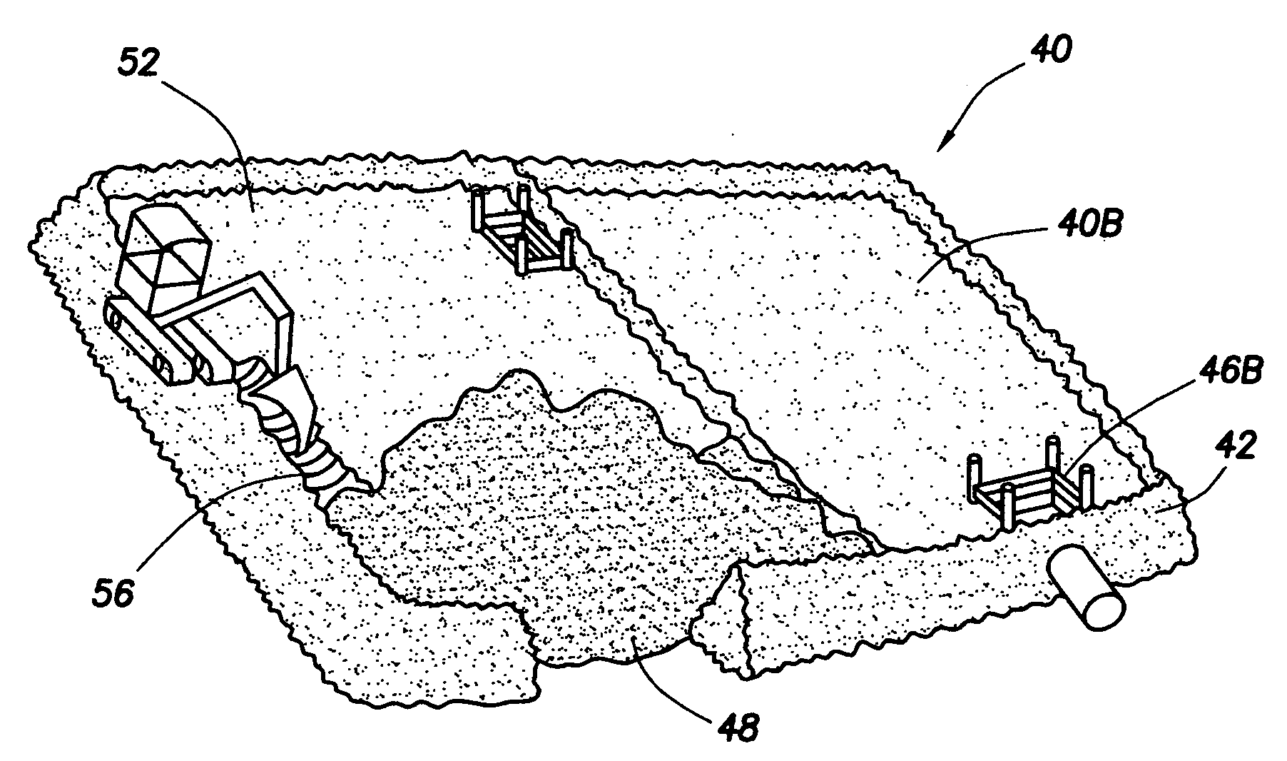
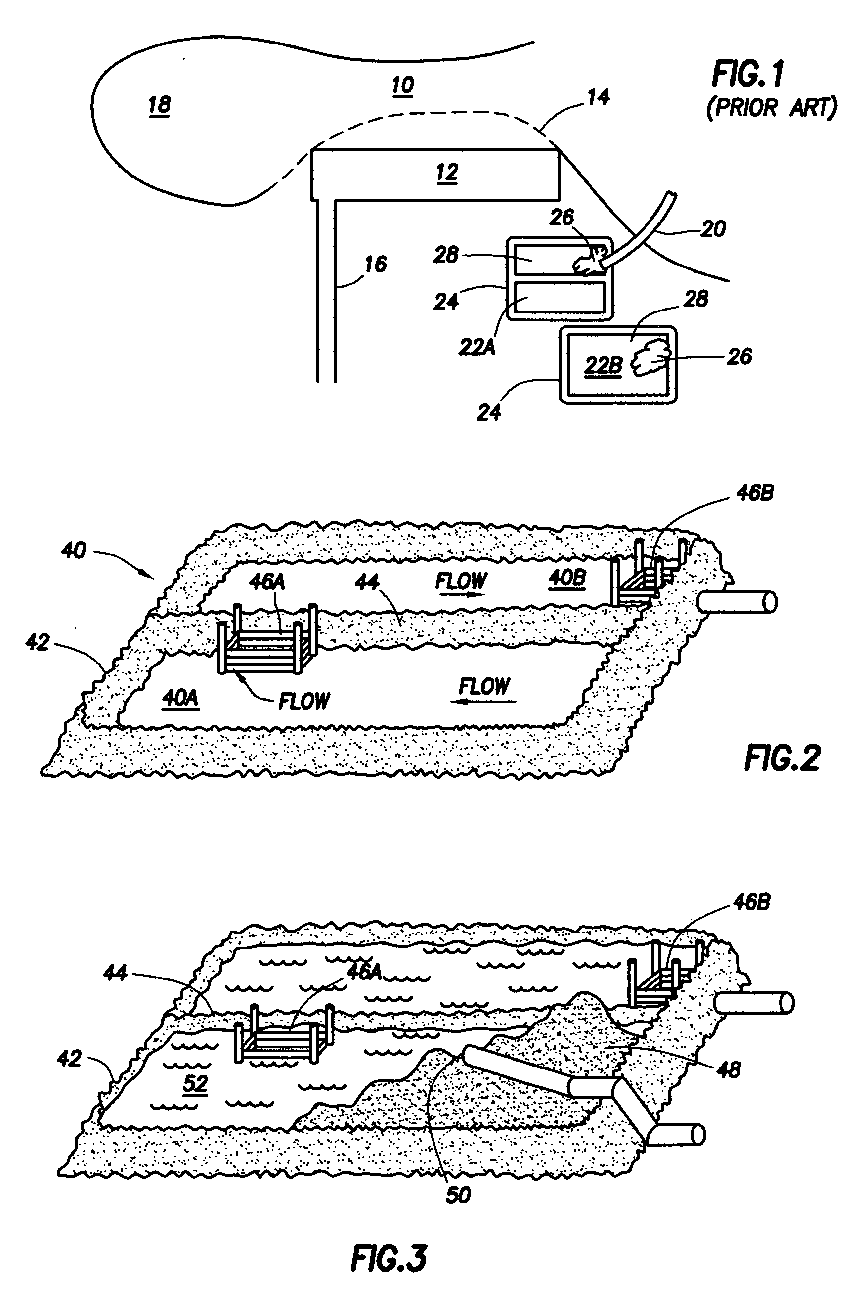
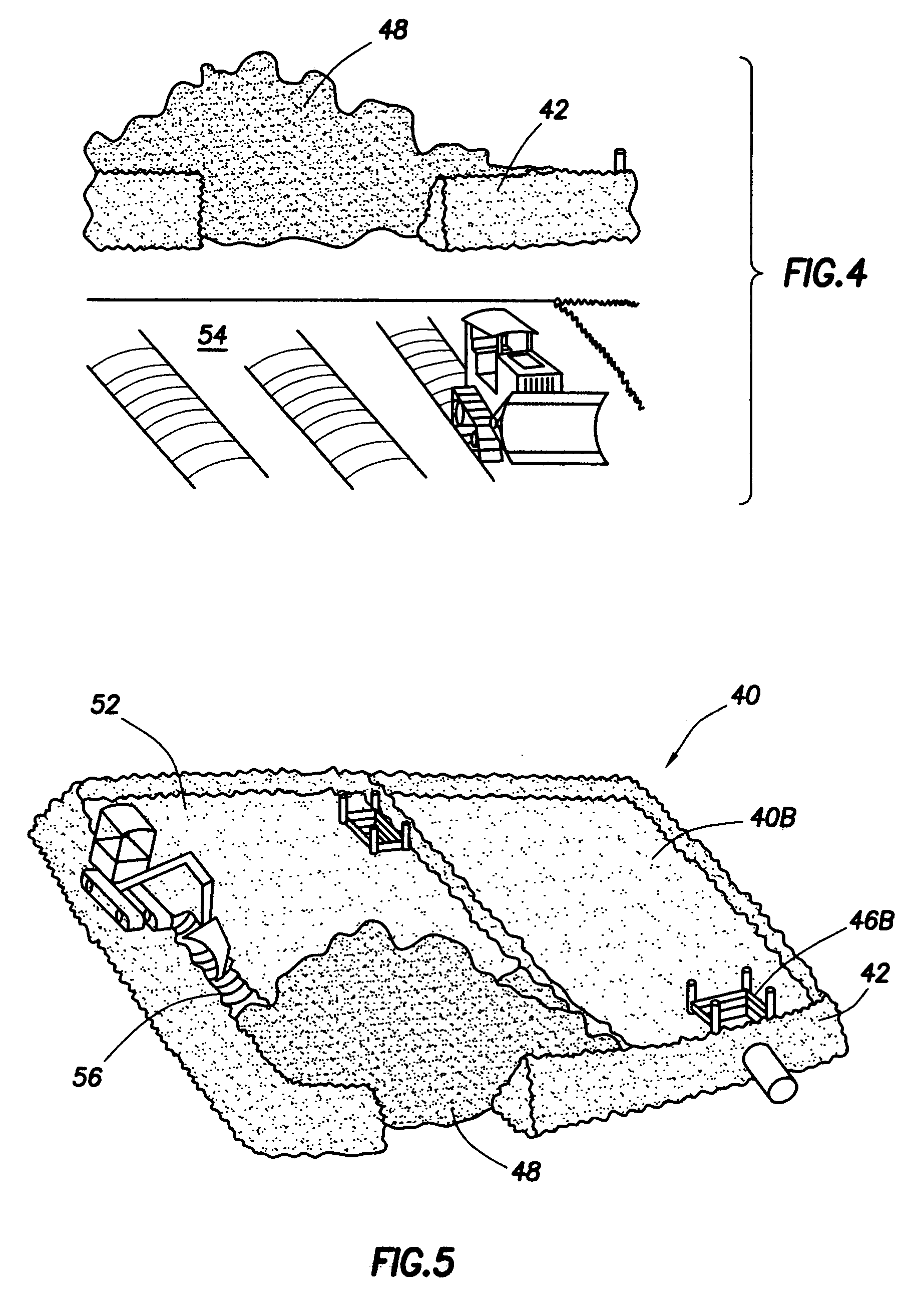
[0020]By contrast, the method of the present invention comprises a series of steps illustrated schematically beginning in FIG. 2. In a first embodiment, the method of the present invention involves the construction of a dredge reclamation area (DRA) 40 on land that is preferably adjacent the channel or waterway to be dredged by enclosing the area 40 by earthen berms 42, the size of DRA 40 being a function of the volume of dredged material to be reclaimed. Training dikes 44 and weirs 46 are built inside DRA 40 to separate DRA 40 into a material holding area 40A from which water escapes while retaining clays and silts pumped into DRA 40 into a clarifying pond 40B, and those skilled in the art will recognize that more than one such dike 44 and two such weirs 46 may be built to separate DRA 40 into multiple holding areas and clarifying ponds as may be required or advantageous depending upon local conditions. The subgrade on which DRA 40 is constructed is graded so that water flows towar...

second embodiment

[0022]In a second embodiment, the method of the present invention comprises the following steps. As shown in FIG. 2, a DRA 40 is constructed by earthen berms 42. A series of training dikes 44 and weirs 46 are constructed in DRA 40 as shown in FIG. 3. As shown in FIG. 8, a drainage swale 62 is then excavated around the perimeter of the wet, silty material 52 in the material holding area 40A of DRA 40 to allow water to drain into the clarifying pond 40B through weir 46A and then out of DRA 40 through weir 46B. As silts 52 are draining, the clay mounds 48 are graded and relatively dry material is windrowed on top as shown at reference numeral 64 in FIG. 9. Windrowing is then repeated with a combination of drying weather and mechanical and / or chemical manipulation for the entire clay mound 58.

[0023]Referring now to FIG. 10, a portion 66 of the graded clay mound area 58 is then excavated down to natural subgrade 68. The natural subgrade 68 is then proof rolled and the dried windrowed cla...


PUM


Abstract

A method for reclaiming hydraulically dredged material from a dredge reclamation area (DRA) having particular application for reclaiming hydraulically dredged virgin/new cut earthen material. The method involves the construction of training dikes and weirs in the DRA for draining water from saturated silts within the DRA and drying clay in the DRA in either a separate processing area or within the confines of the DRA by windrowing and by mechanical manipulation of the clay. The silts are then dried in the same way and mixed with the dried clay, either in a separate processing area or within the DRA. The resulting reclaimed material can meet industry standard density tests of 95% standard Proctor along with removing the moisture content to a 2%± of optimum moisture or better for use as structural or regular fill.

Description

BACKGROUND OF THE INVENTION[0001]The present invention relates to a method for reclaiming hydraulically dredged material. In more detail, the present invention relates to a method by which hydraulically dredged material is processed and dried so that it is reclaimed for use as structural fill or regular fill for construction uses, designs, and / or creating new lands, improving lands, and repairing damaged or lost lands. Although not limited in scope to this particular use, the method of the present invention is particularly suited for reclaiming hydraulically dredged virgin / new cut earthen material (V / NCEM).[0002]Hydraulic dredging is a particularly efficient process for opening a channel or waterway and / or for increasing the depth of an existing channel or waterway. Depending upon the size of the dredging project, hydraulic dredging generates massive quantities of dredged material that is either pumped into nearby waterways, creating hydraulic dredge disposal “island(s),” or into hy...

Claims


Application Information

Patent Timeline
IPC IPC(8): B09C1/00B09B3/00
CPCB09B1/00E02F1/00B09C1/00
Inventor SMITH, TROY A.
Owner SMITH TROY A
Why Eureka
Try Eureka