Occlusion System for Management of Rectal or Anal Incontinence

a technology of occlusion system and rectal or anal incontinence, which is applied in the field of occlusion system, can solve the problems of large consumption of tampon devices of up to 10 per day, difficult and painful removal of swollen tampon bodies by patients, and inability to clean swollen tampon bodies. to achieve the effect of facilitating manipulation

Inactive Publication Date: 2009-06-11
BC & D CONCEPTS
View PDF16 Cites 9 Cited by
  • Summary
  • Abstract
  • Description
  • Claims
  • Application Information

AI Technical Summary

Benefits of technology

[0007]It is one object of this invention to further develop an occlusion system in accordance with a species so that, along with a simplified manipulation thereof, a dependable removal of intestinal gas from the rectum is possible, while easy cleaning of the occlusion system is simultaneously intended to assure repeated use for the patient.

Problems solved by technology

However, such swelled-up tampon bodies are very difficult and very painful for the patient to remove.
Also, the tampon body, which is unfolded and swollen, is often considered to be irritating by the patient and triggers an impulse to defecate, or respectively triggers the defecation effect.
Also, swollen tampon devices are not capable of being cleaned and are therefore one-way products, which cannot be used again, which leads to a large consumption of tampon devices of up to 10 per day.
However, manipulating the known occlusion system leaves room for improvement and furthermore, the removal of intestinal gases through the occlusion system is difficult, because it is necessary for the distal, as well as the proximal ends, to be designed to be open in order to assure the passage of intestinal gas through the shaft element of the occlusion system, which otherwise seals the intestines.
Thus, fecal matter can easily enter into the shaft element, and then exits in an undesired manner via the proximal end, or else causes a stoppage of the gas passage within the continuous lumen of the shaft element.

Method used


Image

  • Occlusion System for Management of Rectal or Anal Incontinence
  • Occlusion System for Management of Rectal or Anal Incontinence

Examples


Embodiment Construction

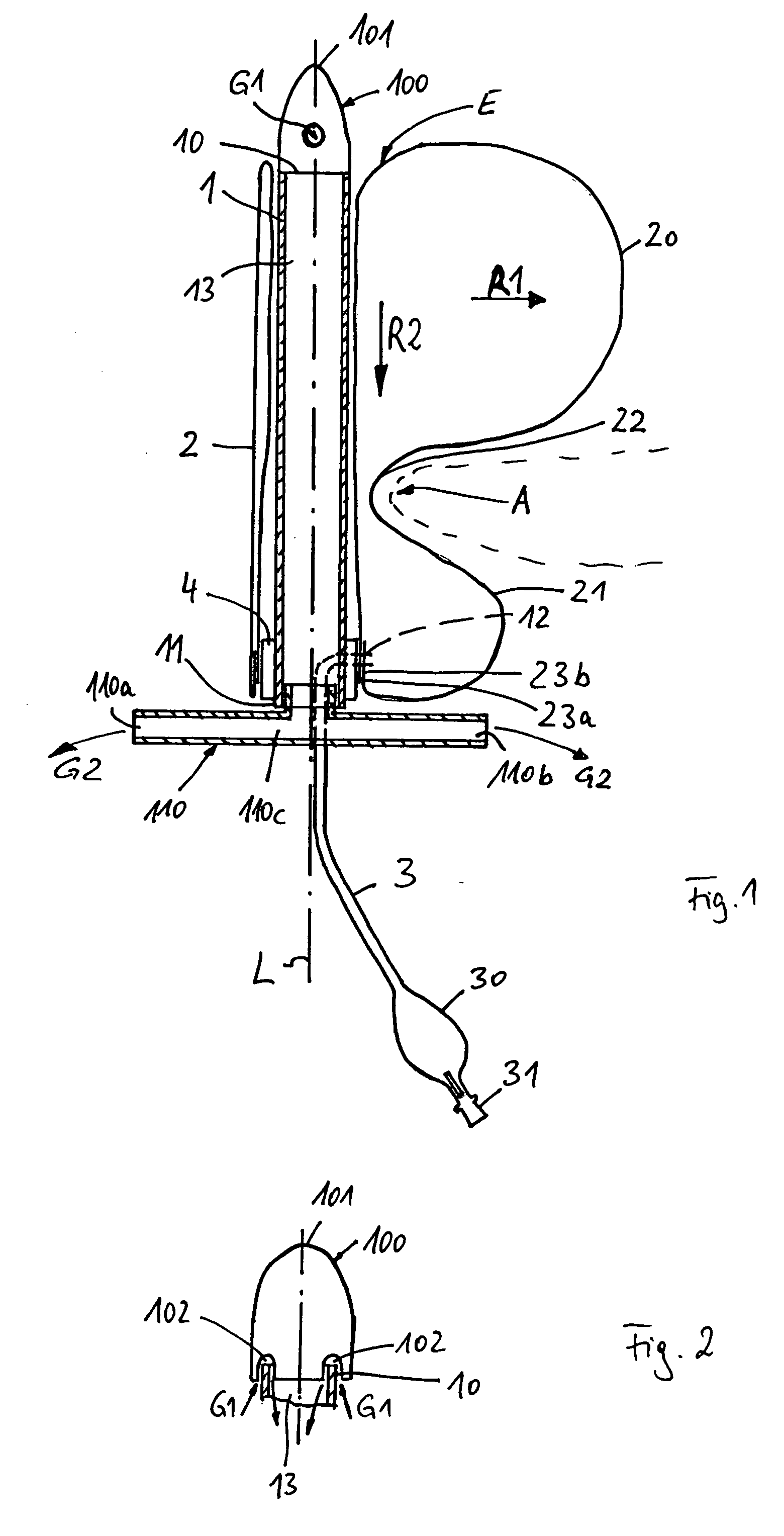
[0032]An occlusion system for managing rectal, or respectively anal, incontinence is represented in FIG. 1, and comprises a central shaft element 1, for example made as an elastically deformable plastic tube having a distal end 10 and a proximal end 11, as well as a lumen 13 extending continuously from the distal end 10 to the proximal end 11 and open at both ends.

[0033]A balloon 1, made from a hose section of a polyurethane foil of a wall thickness of, for example, 15 μm, is fastened in a manner to be described in greater detail later on the shaft element, and can be filled with a filler medium for expanding it via a filler line 3 and a corresponding perforation 12.

[0034]The distal end 10 of the shaft element 1 has an end cap 100, while an outlet tube 110, extending transversely with respect to the longitudinal axis L of the shaft element 1, is provided at the proximal end 11 of the shaft element 1.

[0035]The balloon 2 fastened to the shaft element 1 is shown in two states, which di...


PUM


Abstract

An occlusion system for management of rectal or anal incontinence, including a shaft element with a distal end and a proximal end and with a lumen extending all the way from the distal end to the proximal end of the shaft element. A balloon is mounted adhesively and sealingly on the shaft element and can be filled with a filing medium via a filing line, wherein the balloon is formed from a tube section and is shaped so that when filled with the filing medium it forms a first balloon configuration as an intrarectal balloon and a second balloon configuration as an abutment balloon, which are delimited from each other by a constriction. The distal end of the shaft element is designed with an end cap with a tip and, at a distance from the tip, at least one gas inlet opening provides communication with the lumen of the shaft element. The proximal end of the shaft element is connected to an outlet tube which extends transverse to the longitudinal axis of the shaft element, and has outlet openings at its ends and communicates with the lumen.

Description

BACKGROUND OF THE INVENTION[0001]1. Field of the Invention[0002]This invention relates to an occlusion system for managing rectal, or respectively anal incontinence, including a shaft element with a distal end and a proximal end, a lumen extending continuously from the distal end to the proximal end of the shaft element, and a balloon fixedly and sealingly attached to the shaft element and that can be charged with a filler medium via a filler line. The balloon is of a hose section and when filled with the filler medium, it forms a first balloon deformation as an intra-rectal balloon and a second balloon deformation as a support balloon, which are delimited from each other by a constriction.[0003]2. Discussion of Related Art[0004]Up to now, rectal tampon devices made of a foam material or cellulose material capable of swelling and unfolding automatically are used for taking care of patients with rectal, or respectively anal incontinence, which are inserted by the patient in the form ...

Claims


Application Information

Patent Timeline
Patent Type & Authority Applications(United States)
IPC IPC(8): A61M29/00
CPCA61F5/0093A61F2/0013
Inventor GOBEL, FRED
Owner BC & D CONCEPTS
Why Eureka
Try Eureka