
Device for guiding an element in an orifice in a wall of a turbomachine combustion chamber

a technology of orifice and combustion chamber, which is applied in the direction of machines/engines, combustion types, lighting and heating apparatus, etc., can solve the problems of inability to control welding spillage, inability to operate welding parts of the bushing, and inability to operate properly, etc., to achieve simple, effective and inexpensive

Active Publication Date: 2009-06-18
SN DETUDE & DE CONSTR DE MOTEURS DAVIATION S N E C M A
View PDF7 Cites 16 Cited by
  • Summary
  • Abstract
  • Description
  • Claims
  • Application Information

AI Technical Summary

Benefits of technology

[0012]A particular object of the invention is to provide a solution to this problem that is simple, effective, and inexpensive.
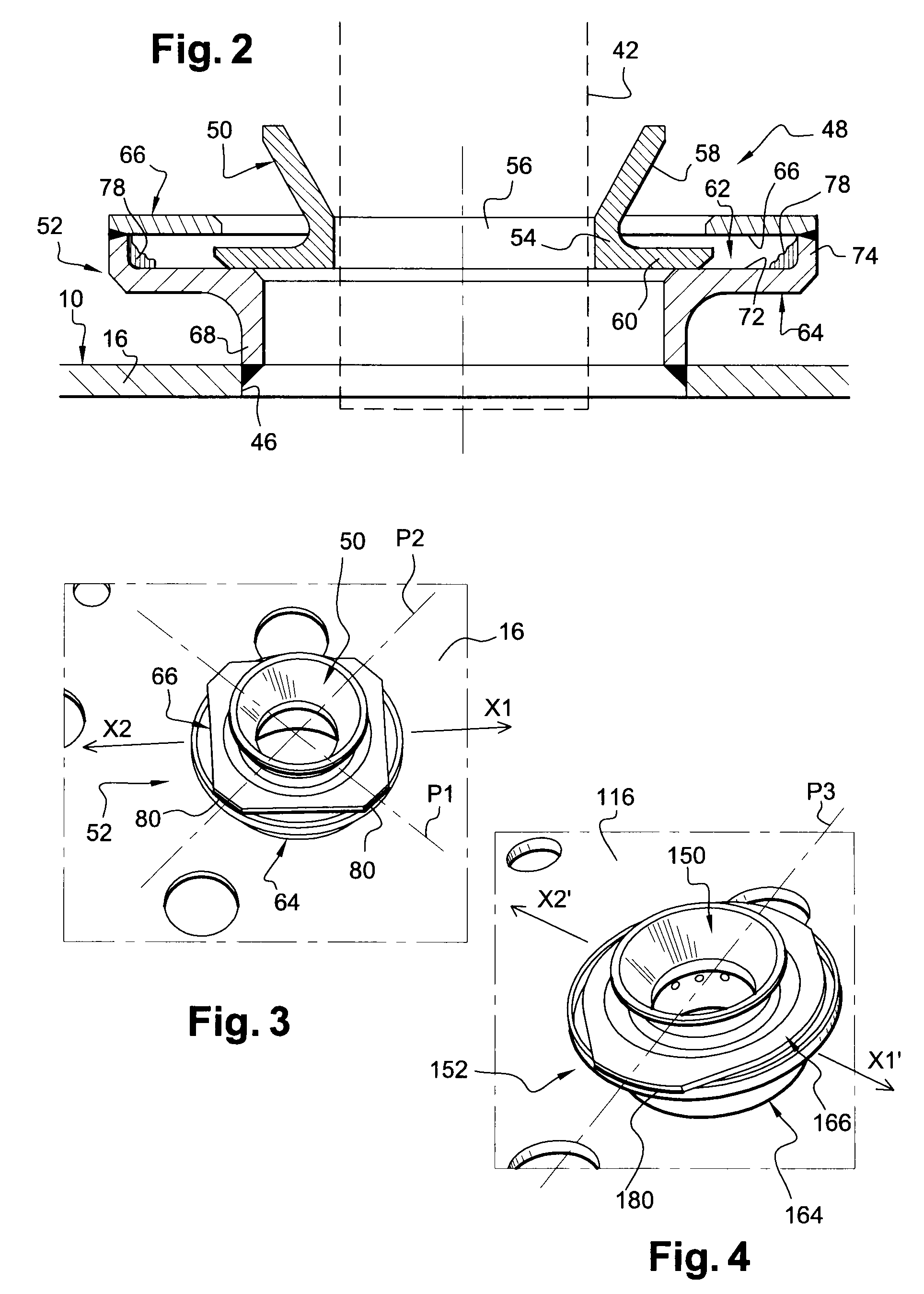
[0014]According to the invention, the two zones of welding or brazing between the two parts of the bushing are not situated on the privileged direction of ring movement, so any spillage of welding or brazing beads penetrating into the groove of the bushing and locally obstructing it will not limit movement of the rim of the ring in the privileged direction. There is therefore no need to make allowance for projections of welding beads when dimensioning the bushing of the guide device. In a particular embodiment of the invention, this makes it possible to reduce the diameter of the bushing by about 2 millimeters (mm) compared with the prior art.
[0016]There may be two of these zones, which zones are then diametrically opposite about the axis of the bushing. By way of example, one of the two parts of the bushing is a washer having an outline that is substantially oval or oblong, the washer having end portions of smaller radius of curvature that are brazed or welded to the other part of the bushing. This particular shape for the washer of the bushing enables the weight of the device to be reduced. Advantageously, the welding or brazing zones are in alignment on an axis that is substantially perpendicular to the privileged direction of ring movement.

Problems solved by technology

The operation of welding the parts of the bushing is thus difficult to perform and does not enable welding spillage to be controlled.
Furthermore, there is a significant risk of the device being blocked or jamming each time the rim of the ring comes into contact with a welding bead projecting into the groove of the bushing, with an associated unacceptable risk of the spark plug or the injector being broken.
Nevertheless, that solution is unsatisfactory since it leads to a significant increase in the weight of the device and it would impede ventilation of the wall of the combustion chamber by partially overlapping air-passing orifices in said wall situated in the vicinity of the device.

Method used


Image

  • Device for guiding an element in an orifice in a wall of a turbomachine combustion chamber
  • Device for guiding an element in an orifice in a wall of a turbomachine combustion chamber
  • Device for guiding an element in an orifice in a wall of a turbomachine combustion chamber

Examples


Embodiment Construction

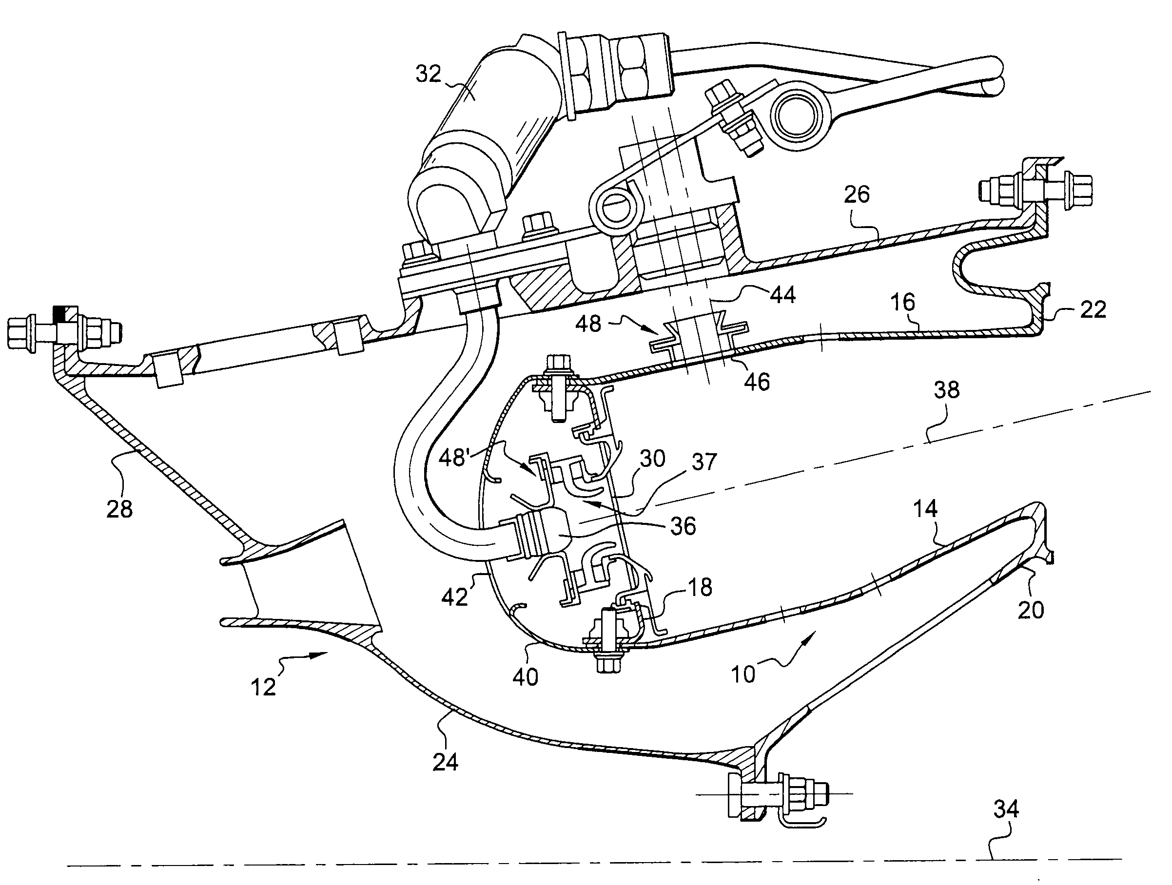
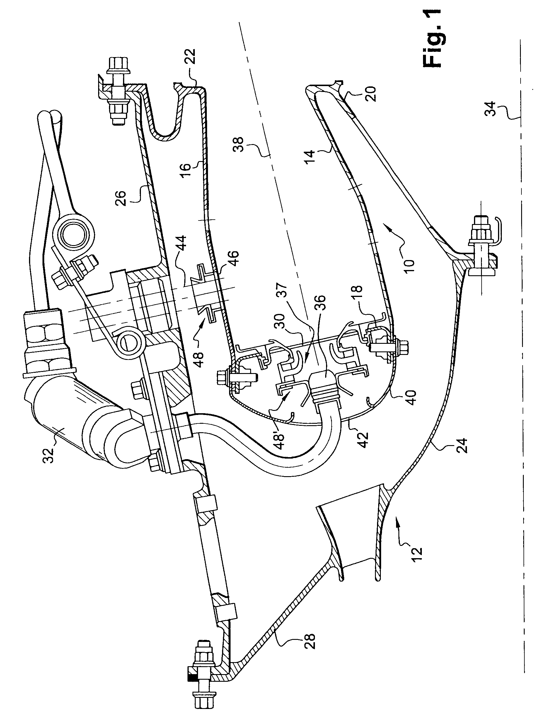
[0024]With reference initially to FIG. 1, there can be seen an annular combustion chamber 10 for a turbomachine such as an airplane turbojet, arranged at the outlet from an annular diffuser 12, itself situated at the outlet from a compressor (not shown).

[0025]The chamber 10 comprises an inner wall 14 and an outer wall 16 both in the form of bodies of revolution, which walls are connected together at their upstream ends by an annular chamber end wall 18, and are fastened at their downstream ends via inner and outer annular flanges 20 and 22 respectively to an inner frustoconical partition 24 of the diffuser and to a downstream end of an outer casing 26 of the combustion chamber, the upstream end of said casing 26 being fastened to an outer frustoconical partition 28 of the diffuser.

[0026]The chamber end wall 18 includes orifices 30 for mounting systems 37 to inject a mixture of air and fuel into the chamber 10, the air coming from the diffuser 12 and the fuel being delivered by injec...


PUM

PropertyMeasurementUnit
angleaaaaaaaaaa
diameteraaaaaaaaaa
radius of curvatureaaaaaaaaaa

Abstract

A device for guiding an element in an orifice in a wall of a turbomachine combustion chamber comprises a coaxial ring and bushing mounted one inside the other, the bushing comprising two coaxial annular parts that are fastened to each other by welding and that define a groove for guiding a rim of the ring, welding zones between the parts of the bushing being situated away from the path of the rim of the ring when moved along a privileged transverse direction of ring movement relative to the bushing when the combustion chamber is in operation.

Description

FIELD OF THE INVENTION [0001]The present invention relates to a device for guiding an element such as an ignition spark plug or a fuel injector that extends through an orifice or in the vicinity of an orifice in a wall of a turbomachine combustion chamber.BACKGROUND OF THE INVENTION [0002]An annular combustion chamber of a turbomachine is defined by two walls in the form of bodies of revolution that are coaxial with one extending inside the other and that are connected together at their upstream ends by an annular end wall of the chamber.[0003]The chamber end wall includes orifices for mounting means for injecting a mixture of air and fuel into the combustion chamber, the air coming from a compressor of the turbomachine and the fuel being delivered by injectors. The injectors extend substantially radially from their outer ends that are fastened on an outer casing of the combustion chamber, and they have heads that are aligned axially with the orifices in the chamber end wall.[0004]T...

Claims


Application Information

Patent Timeline
Patent Type & Authority Applications(United States)
IPC IPC(8): F02C7/20F02C7/22F02C7/266
CPCF23R3/002F23R3/283Y10T29/49348F23R3/60F23R2900/00012F23R3/50
Inventor AUDIN, PATRICKBESSAGNET, FLORIAN ANDRE FRANCOISSABLAYROLLES, PIERRE PASCALSEVI, GUILLAUME
Owner SN DETUDE & DE CONSTR DE MOTEURS DAVIATION S N E C M A
Learn More