
Ultrasonic Testing System and Ultrasonic Testing Technique for Pipe Member

a testing system and ultrasonic technology, applied in the direction of instruments, specific gravity measurement, magnetic property measurement, etc., can solve the problems of troublesome position adjustment and the like, troublesome, and the problem of not being able to achieve the optimal conditions, and achieve the effect of easy setting optimum conditions

Active Publication Date: 2009-06-18
JFE STEEL CORP
View PDF35 Cites 23 Cited by
  • Summary
  • Abstract
  • Description
  • Claims
  • Application Information

AI Technical Summary

Benefits of technology

[0016]An object of the present invention, which was made in view of the above circumstances, is to provide an ultrasonic testing system and an ultrasonic testing technique for a pipe member having a first object of detecting minute flaws of about several hundreds of micron meters or less, which occur in the wall thickness inside portion of a welded portion of a welded steel pipe and the like from an inside surface to an outside surface without omitting them and a second object of easily setting optimum conditions when a pipe size is changed.

Problems solved by technology

In contrast, recently, since very severe quality is required to a welded steel pipe, it is required to detect flaws smaller than conventional ones.
However, the problems described below still remain even in the techniques disclosed above.
First, the technique of Patent Document 1 has a problem in that many channels are necessary to detect the flaws in the entire area in the depth direction of a welded portion (wall thickness direction of steel pipe) without omitting them because the beam width of a focused ultrasonic wave is narrow and thus an equipment cost becomes expensive and further in that when a pipe size is changed, a position adjustment and the like are troublesome.
Further, when a flaw is not a blowhole shape and is a plane shape as that in a penetrator and a cold joint as well as a flaw is located in a wall thickness inside portion, it is difficult to detect the flaw because an echo travels in a direction different from a direction of incidence.
However, the latter problem still remains unsolved.
Accordingly, an echo from the flaw is actually very weak even in the techniques of Patent Documents 3 and 4, and thus it is often difficult to detect the flaw.
Further, since an area of about 1 to 2 mm in the vicinity of a surface echo is made to a dead zone by a reverberant surface echo, a problem arises in that when a flaw is located in the vicinity of an outside surface, it cannot be detected.

Method used


Image

  • Ultrasonic Testing System and Ultrasonic Testing Technique for Pipe Member
  • Ultrasonic Testing System and Ultrasonic Testing Technique for Pipe Member
  • Ultrasonic Testing System and Ultrasonic Testing Technique for Pipe Member

Examples


embodiment 1

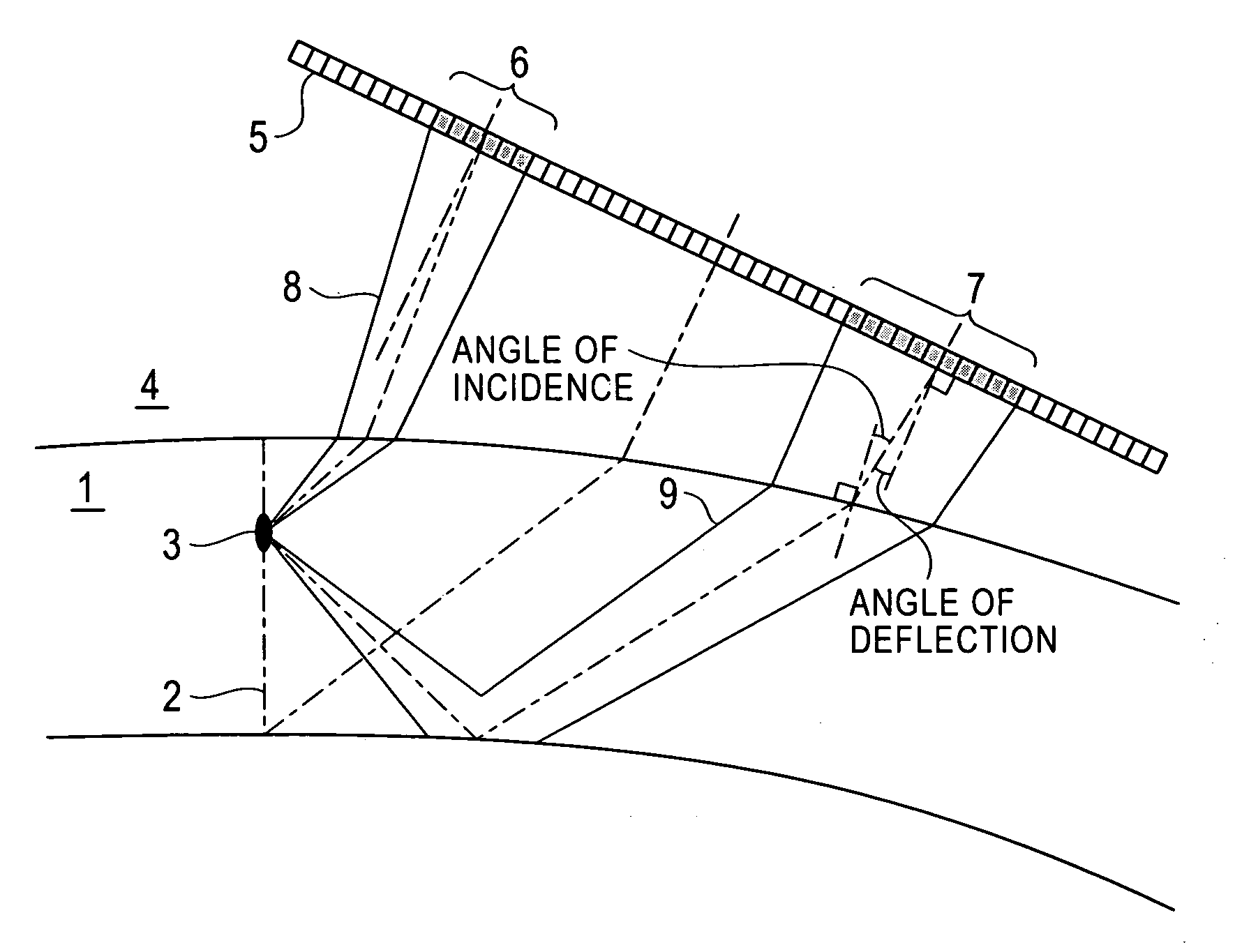
[0119]Embodiments of the present invention will be explained below referring to the figures. FIG. 1 is a view explaining a first embodiment of the present invention. In the figure, 1 denotes a steel pipe as a to-be-tested member,2 denotes a welded portion, 3 denotes a flaw in a wall thickness inside portion, 4 denotes water for transmitting an ultrasonic wave, 5 denotes a linear array probe, 6 denotes a group of transducer elements for transmission, 7 denotes a group of transducer elements for reception, 8 denotes a transmitting beam, and 9 denotes a portion showing the ultrasonic wave traveling from a flaw to the group of transducer elements for receptions (hereinafter, also called a receiving beam), respectively. Further, the lines drawn between the transmitting beam 8 and the receiving beam 9 show scanning lines, respectively.

[0120]The linear array probe 5 has such a size that the ultrasonic wave, which is transmitted from the group of transducer elements located to a side near t...

embodiment 2

[0151]Next, a second embodiment of the present invention will be explained. FIG. 8 is a view explaining the second embodiment of the present invention and shows setting and a procedure of testing at step 3 shown in FIG. 2. In the figure, 7′ to 7″′ show groups of transducer elements for reception, and 9′ to 9″′ show receiving beams. In the embodiment, a transmitting beam 6 is transmitted from a group of transducer elements for transmission 5 and received by the group of transducer elements for reception 7′ first. Next, the transmitting beam 6 is transmitted from the group of transducer elements for transmission 5 and received by the group of transducer elements for receptions 7″. Finally, the beam 6 is transmitted from the group of transducer elements for transmission 5 and received by the group of transducer elements for receptions 7″′. With this operation, even if the position of a welded portion is swung right and left as shown in the figure because the position of a welded point ...

embodiment 3

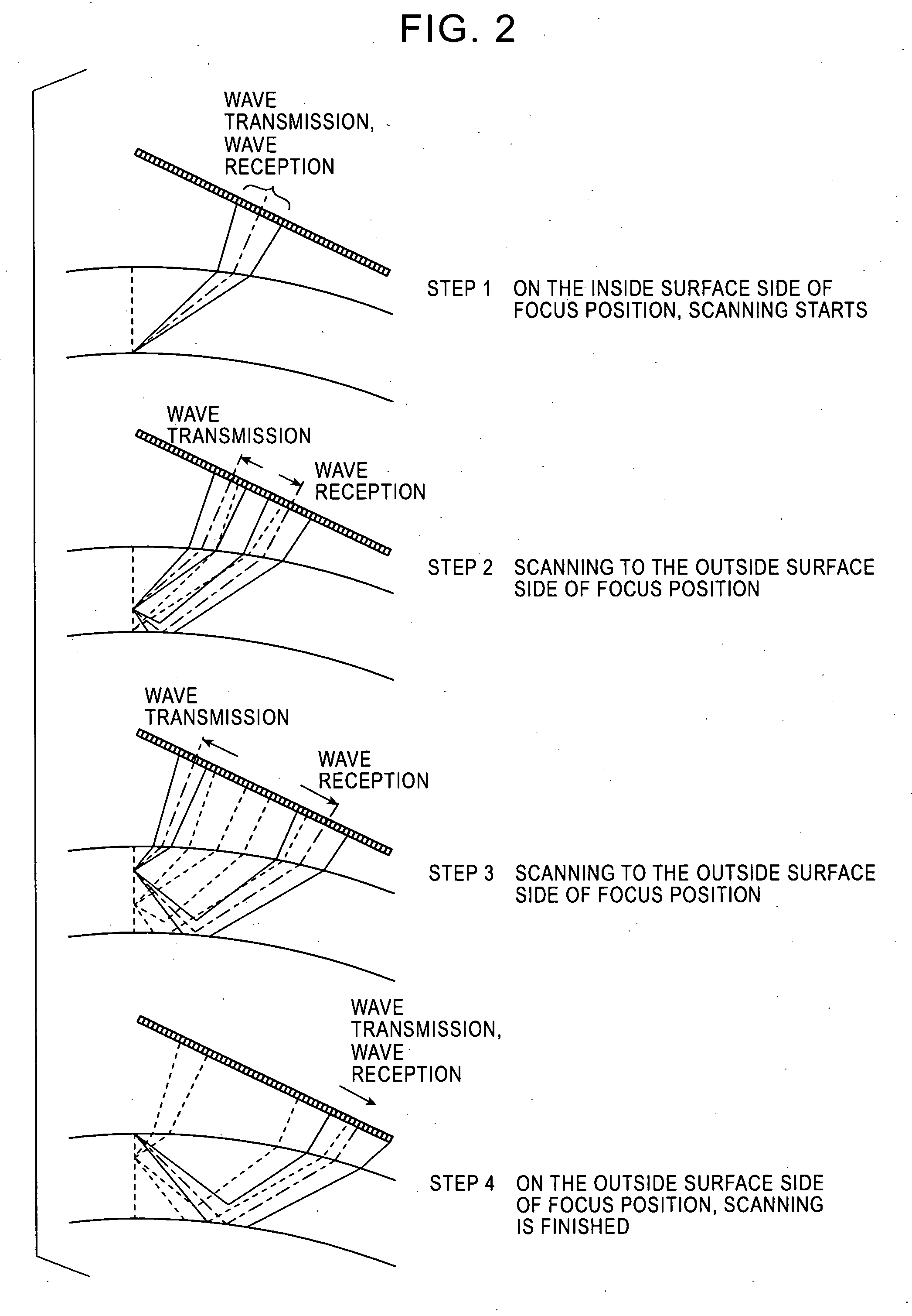
[0152]Next, a third embodiment of the present invention will be explained. FIG. 9 is a view explaining the third embodiment of the present invention. In the third embodiment, after the entire wall thickness of a certain portion in a pipe peripheral direction is tested at steps 1 to 4 of FIG. 2, the proximal side (right side in the figure) of the scanning position is tested at next steps 5 to 8 and further the distal side thereof (left side in the figure) is tested at steps 9 to 12.

[0153]With this operation, even if a flaw is swung right and left because the position of a welded point cannot be specified, a positioning accuracy is bad, vibration occurs, and the like, since scanning lines intersect a welding line by any of the combinations thereof, the flaw can be detected without omission. Although three scanning lines intersect an intersecting position in FIG. 3, the present invention is not limited thereto. The intersecting position of scanning lines can be offset by a technique of...


PUM


Abstract

Disclosed are an ultrasonic testing system and an ultrasonic testing technique for a pipe member capable of detecting minute flaws of several hundreds of microns or less located at positions in the wall thickness inside portion of a welded portion of a seam-welded pipe and the like without omission and further easily setting optimum conditions when the size of the pipe is changed. A transmitting beam, which is focused to the welded portion at an oblique angle, is transmitted using a part of the group of transducer elements of a linear array probe as a group of transducer elements for transmission, a receiving beam, which is focused at the focusing position of the transmitting beam at an oblique angle, is formed using the transducer elements of a portion different from the above group of transducer elements for transmission as a group of transducer elements for reception, and a flaw echo is received from the welded portion.

Description

TECHNICAL FIELD[0001]The present invention relates to an ultrasonic testing system and an ultrasonic testing technique for a pipe member for accurately detecting minute flaws occurring to a welded portion of a welded steel pipe by ultrasonic testing.TECHNICAL FIELD[0002]In a welded steel pipe, the quality of a welded portion is very important, and on-line flaw testing of a welded portion is ordinary carried out by angle beam testing in a manufacturing process. In the technique, an ultrasonic wave is obliquely incident on a surface to be tested of a to-be-tested member, and the flaws of the inside and outside surfaces and the internal flaws of the to-be-tested member are detected from the echo reflected from the flaws. Ordinarily, a reflection technique using an ultrasonic beam of 5 MHz having an angle of refraction of 45° is applied to, for example, a seam-welded pipe, and flaws of the order of millimeters, for example, incomplete penetrations, burn through, cracks due to inclusion,...

Claims


Application Information

Patent Timeline
IPC IPC(8): G01N29/04
CPCG01N29/07G01N29/221G01N2291/0234G01N2291/0421G01N2291/2675G01N2291/0428G01N2291/044G01N2291/106G01N2291/2634G01N2291/0422G01N29/04G01N29/24
Inventor IIZUKA, YUKINORI
Owner JFE STEEL CORP
Features
  • Generate Ideas
  • Intellectual Property
  • Life Sciences
  • Materials
  • Tech Scout
  • Unparalleled Data Quality
  • Higher Quality Content
  • 60% Fewer Hallucinations
Learn More