
Arrangement comprising two elements which can be rotatably displaced in respect of one another

a technology of rotationally displaced elements and arrangement, applied in the direction of optical radiation measurement, photometry using electric radiation detectors, instruments, etc., can solve the problems of scattering loss and achieve the effect of simple production, easy metalization, and extremely small tolerances

Inactive Publication Date: 2009-06-18
SIEMENS AG
View PDF5 Cites 1 Cited by
  • Summary
  • Abstract
  • Description
  • Claims
  • Application Information

AI Technical Summary

Benefits of technology

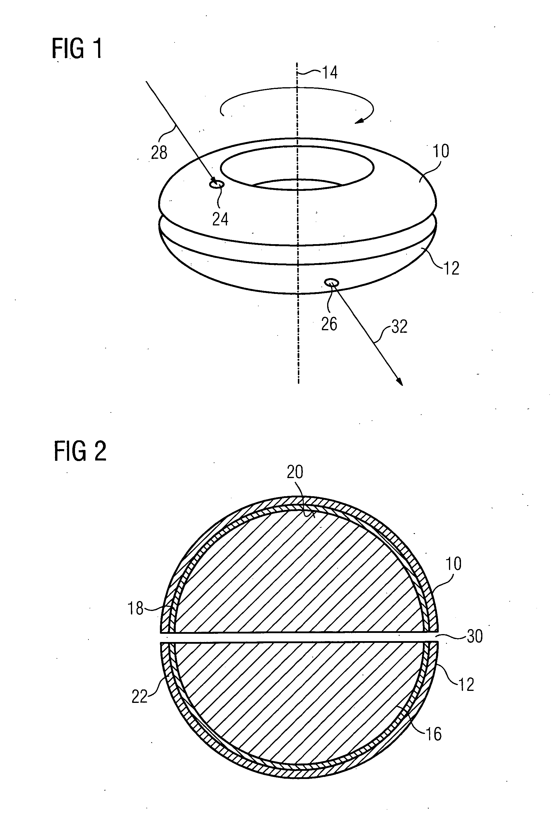
[0005]The semicircular cross-sections of the inner surfaces of the two cover bodies ideally extend to form a circle, namely preferably such that each cover body provides a semicircular cross-section. This means nothing other than that the space defined by the inner surface is precisely half of a torus, and the space of the other element which is defined by the inner surface is the second half of the torus in each instance. Such an arrangement is particularly easy to manufacture, by an annular optical fiber with a circular cross-section being easily divided into two parts, which are arranged opposite to one another on different elements. In this case, the cover bodies, like the optical fibers, usually surround an annular optical fiber core in each instance, namely the material from which the optical fiber core is formed has a greater refractive index than the material from which the cover body is formed. Light is then knowingly reflected onto the inner surface of the cover body.
[0007]With a particularly simple embodiment, air is used very simply as fluid. The inner surface of the cover body can be very easily metalized.
[0009]The embodiments, in which the fluid is used, are advantageous in that no transitions exist between different media, so that no losses occur in the light beam power until the light beam reaches the light receiver. It is then possible to potentially operate using a weaker light source and / or a less sensitive light receiver than in the case of the embodiment with the optical fiber halves.

Problems solved by technology

The advantage of the simple producibility is gained by the disadvantage that the tolerances are extremely small, thereby concerning the gap between the two torus halves.
Scattering losses occur in the case of all these transitions.

Method used


Image

  • Arrangement comprising two elements which can be rotatably displaced in respect of one another
  • Arrangement comprising two elements which can be rotatably displaced in respect of one another
  • Arrangement comprising two elements which can be rotatably displaced in respect of one another

Examples


Embodiment Construction

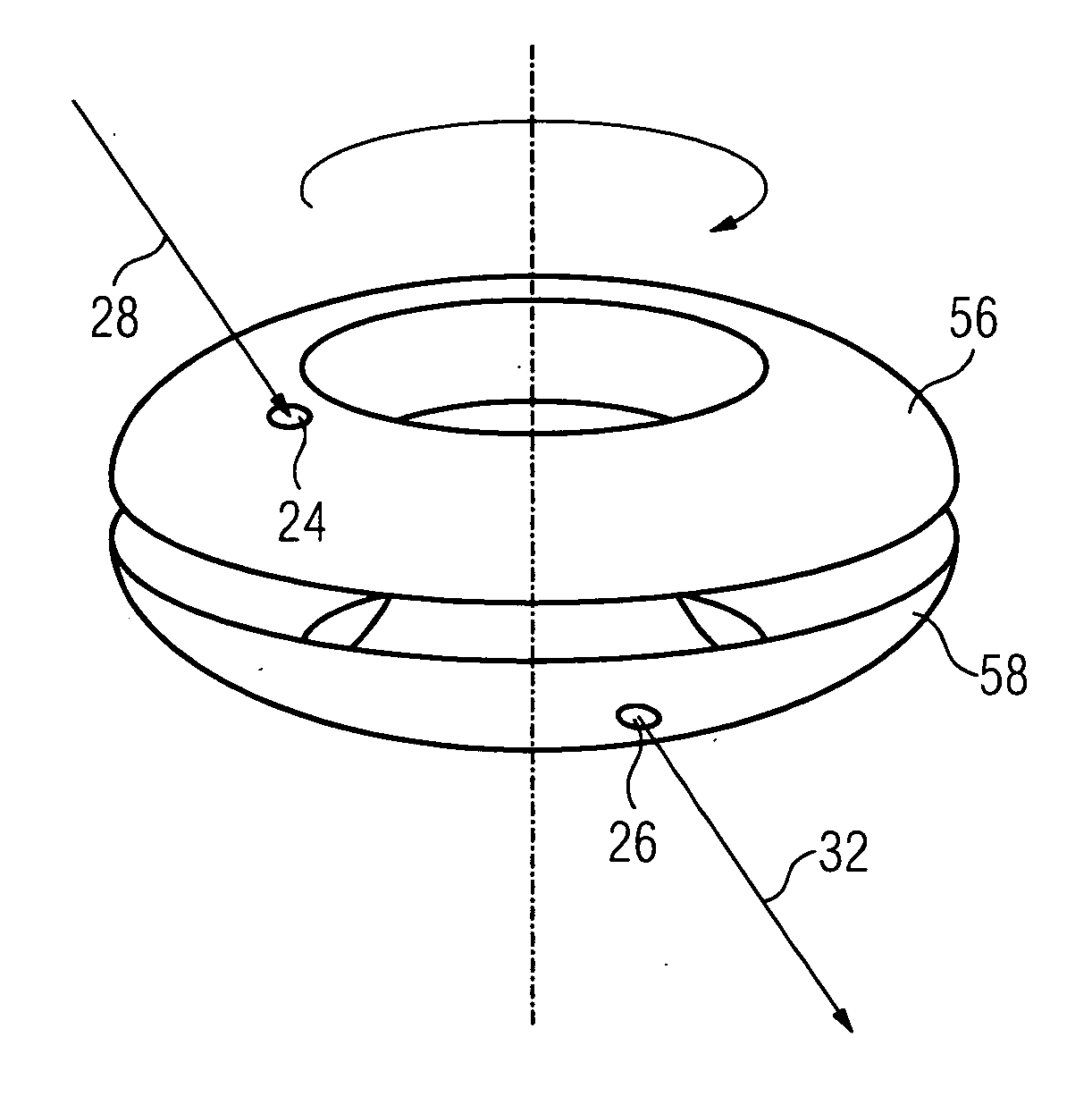
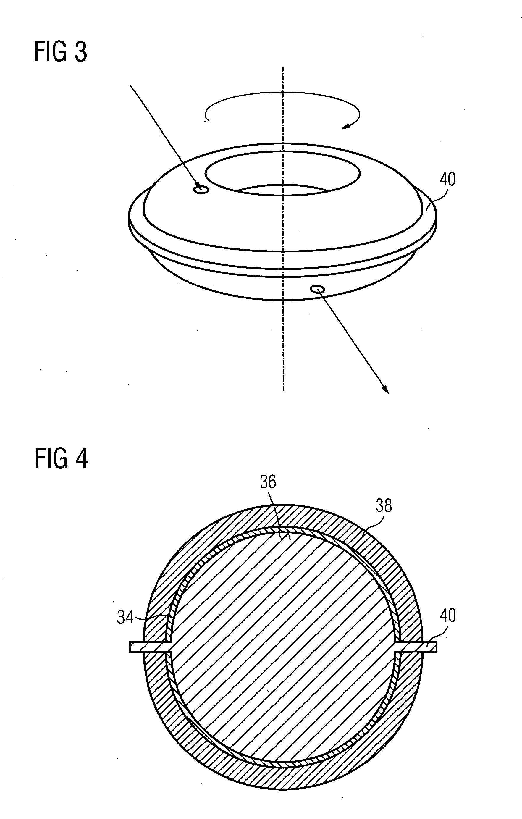
[0019]This currently concerns a machine, on which an element can be rotated, typically opposite to an element which is fixed in the space. It is now frequently necessary in the case of modern applications that information is transmitted from the fixed element to the rotating element or vice versa. With the present invention, it is common to different embodiments that they are suited to the rotation taking place by way of a hollow shaft, so that no exchange of data is possible in the axis of rotation. It is common to all embodiments that the data communication takes place by way of optical signals. The present embodiments allow only one single light source and one single light receiver to have to be used. Three different embodiments are shown in FIGS. 1, 3 and 7, namely neither the individual elements are shown, nor light sources and light receivers, but instead only the medium, by way of which the light is transmitted from the light source to the light receiver.

[0020]With the embodi...


PUM


Abstract

Data is to be exchanged between a rotating element and a further element, with the rotating element being rotated by way of a hollow shaft. Light is coupled into torus halves and is reflected into a torus half and onto torus inner walls so often by way of a small opening until it exits at an opening of the other torus half. In a first embodiment, a torus-shaped optical fiber is divided into two torus halves. In another embodiment, hollow tori are used, which are filled with a fluid, namely either with a liquid or with air.

Description

CROSS REFERENCE TO RELATED APPLICATIONS[0001]This application claims priority of European Patent Office application No. 07024424.9 EP filed Dec. 17, 2007, which is incorporated by reference herein in its entirety.FIELD OF INVENTION[0002]The invention relates to an arrangement comprising two elements, of which the one element can be rotated about an axis of rotation relative to the other element, with a device enabling the communication from the one to the other element being arranged on both elements. Such an arrangement is needed in the case of modern machine concepts, e.g. with rotary indexing machines and production machines. Data communication is usually effected in a wired fashion. If continuous rotation is to be enabled, a wireless transmission by way of a rotatable interface is necessary. It is known to allow the data communication to take place by way of light signals. This can be easily achieved by a light emitter being arranged on the one element and a light receiver being...

Claims


Application Information

Patent Timeline
IPC IPC(8): G02B27/00H04B10/00
CPCH04B10/22G02B6/3604H04B10/801
Inventor DENK, JOACHIMSCHIERLING, HUBERT
Owner SIEMENS AG
Learn More