Touch panel and display device using the same

Active Publication Date: 2009-06-18
TSINGHUA UNIV +1
View PDF99 Cites 102 Cited by
  • Summary
  • Abstract
  • Description
  • Claims
  • Application Information

AI Technical Summary

Problems solved by technology

The transparent conductive layers (e.g., ITO layers) are generally formed by means of ion-beam sputtering, and this method is relatively complicated.
Furthermore, the ITO layers have generally poor mechanical durability, low chemical endurance, and unev

Method used


Image

  • Touch panel and display device using the same
  • Touch panel and display device using the same
  • Touch panel and display device using the same

Examples


Embodiment Construction

[0021]Reference will now be made to the drawings to describe, in detail, embodiments of the present touch panel and display device using the same.

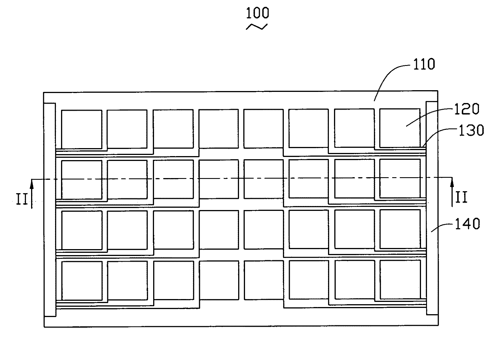
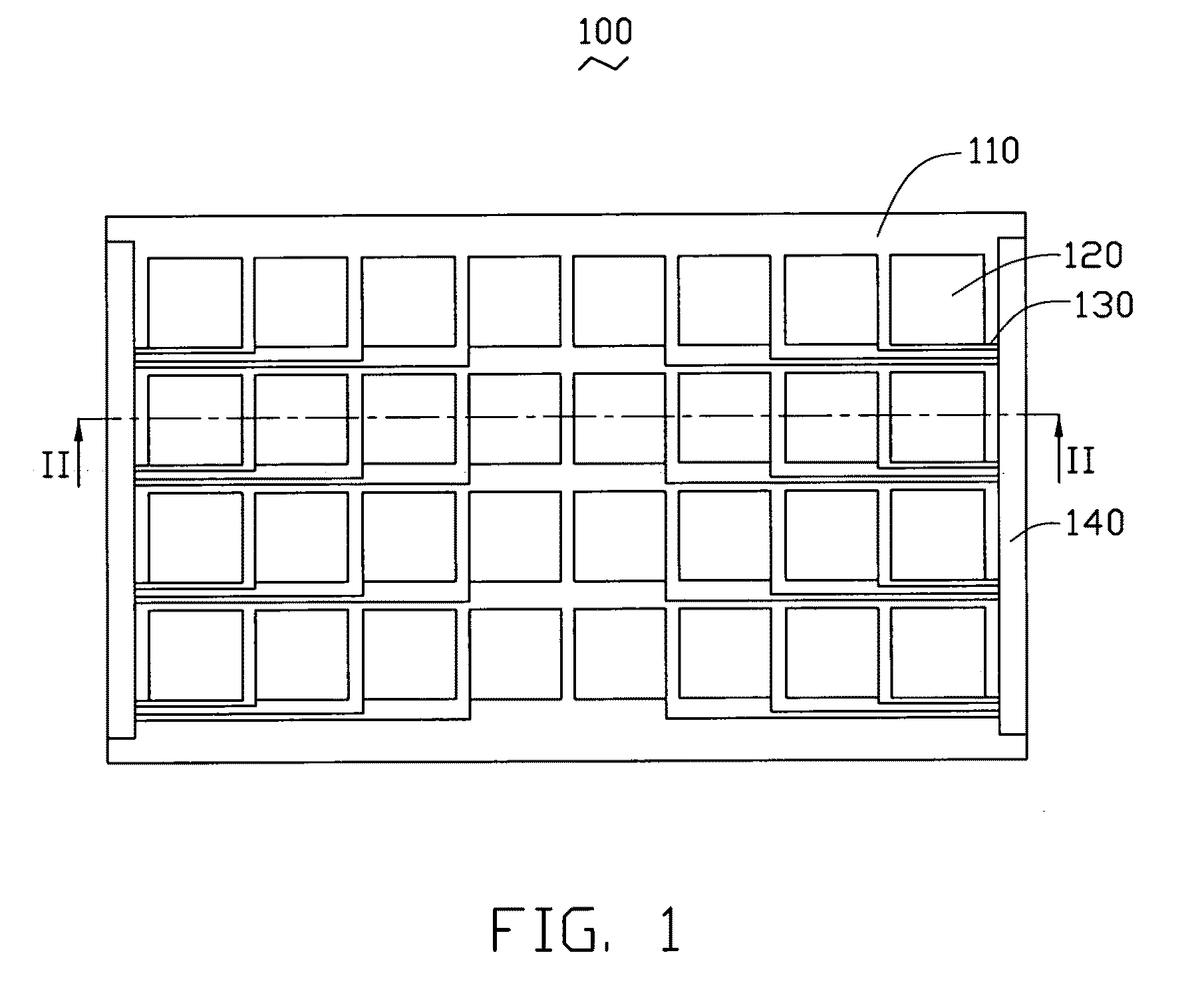
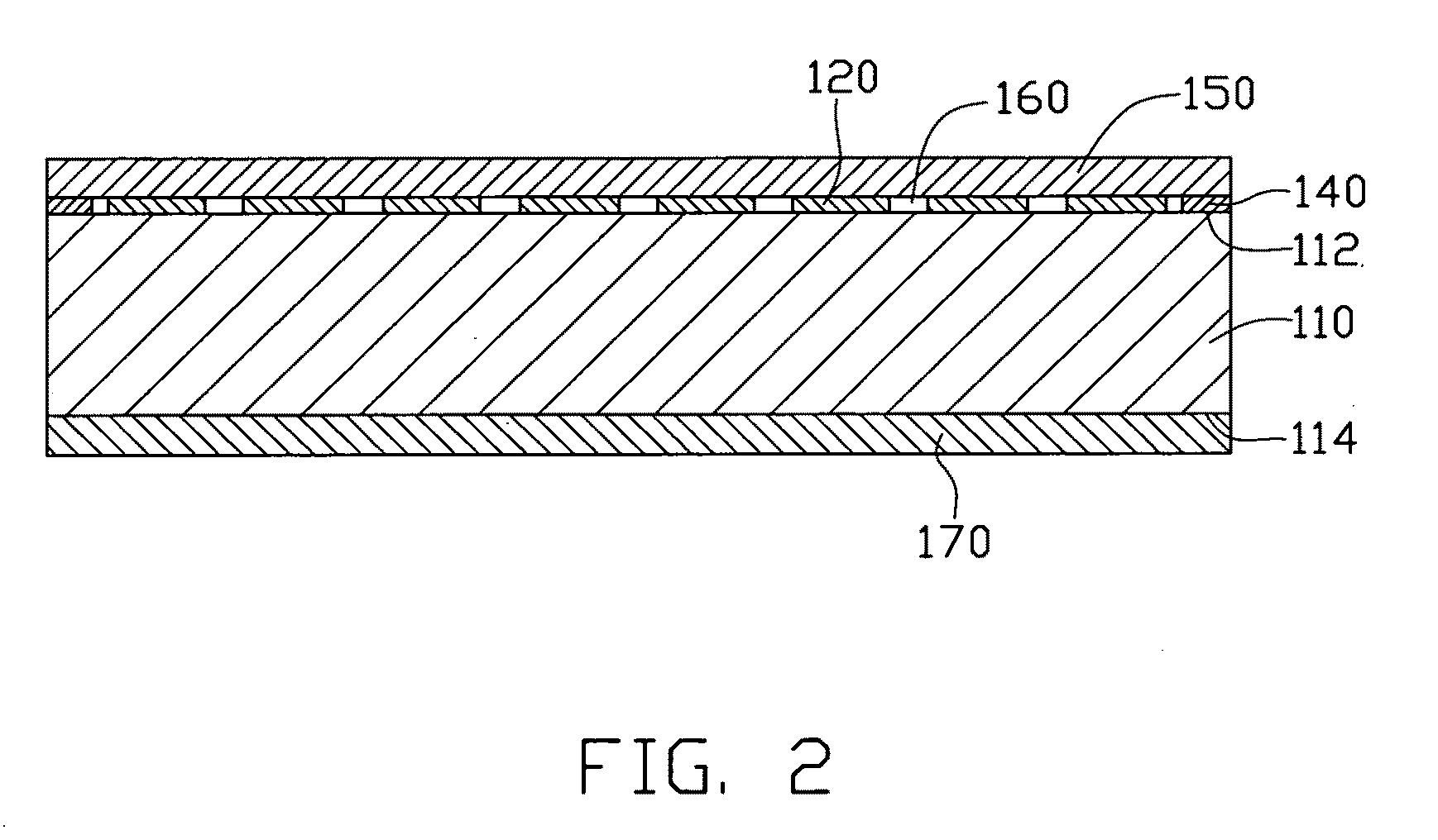
[0022]Referring to FIG. 1 and FIG. 2, a touch panel 100 includes a substrate 110, a plurality of transparent conductive layers 120, a plurality of conductive wires 130, at least one capacitive sensing circuit 140, a transparent protective film 150, and a filling layer 160. The substrate 110 has a first surface 112 and a second surface 114 at opposite top and bottom sides thereof respectively. The transparent conductive layers 120 and the conductive wires 130 are disposed on the first surface 112 of the substrate 110. All the transparent conductive layers 120 are spaced apart from each other and electrically isolated from each other. That is, transparent conductive layers 120 are arranged in a matrix with gaps defined therebetween. In the illustrated embodiment, there are two capacitive sensing circuits 140, which are positioned at opposite...


PUM

PropertyMeasurementUnit
Thicknessaaaaaaaaaa
Thicknessaaaaaaaaaa
Angleaaaaaaaaaa

Abstract

An exemplary touch panel includes a substrate, transparent conductive layers, a capacitive sensing circuit, and conductive wires. The transparent conductive layers are disposed on a surface of the substrate and spaced apart from each other. Each transparent conductive layer includes a carbon nanotube layer. The carbon nanotube layer includes carbon nanotubes. The conductive wires respectively electrically connect the transparent conductive layers to the capacitive sensing circuit. A display device using the touch panel is also provided.

Description

RELATED APPLICATIONS[0001]This application is related to commonly-assigned applications entitled, “TOUCH PANEL”, filed ______ (Atty. Docket No. US17449); “TOUCH PANEL AND DISPLAY DEVICE USING THE SAME”, filed ______ (Atty. Docket No. US17818); “TOUCH PANEL AND DISPLAY DEVICE USING THE SAME”, filed ______ (Atty. Docket No. US17889); “TOUCH PANEL AND DISPLAY DEVICE USING THE SAME”, filed _______ (Atty. Docket No. US17861); “TOUCH PANEL”, filed ______ (Atty. Docket No. US17448); “ELECTRONIC ELEMENT HAVING CARBON NANOTUBES”, filed ______ (Atty. Docket No. US18066); “TOUCH PANEL AND DISPLAY DEVICE USING THE SAME”, filed ______ (Atty. Docket No. US17862); “TOUCH PANEL AND DISPLAY DEVICE USING THE SAME”, filed ______ (Atty. Docket No. US17863); “TOUCH PANEL AND DISPLAY DEVICE USING THE SAME”, filed ______ (Atty. Docket No. US18263); “TOUCHABLE CONTROL DEVICE”, filed ______ (Atty. Docket No. US18262); “TOUCH PANEL AND DISPLAY DEVICE USING THE SAME”, filed ______ (Atty. Docket No. US17888); ...

Claims


Application Information

Patent Timeline
IPC IPC(8): G06F3/041
CPCG06F3/0416Y10T428/269G06F2203/04107G06F3/044G06F3/0443
Inventor JIANG, KAI-LILIU, LIANGFAN, SHOU-SHAN
Owner TSINGHUA UNIV
Why Eureka
Try Eureka