Light source device, projector, and driving method of discharge lamp

a technology of light source device and discharge lamp, which is applied in the direction of light source, projector, instrument, etc., can solve the problems of excessive degradation of the electrode at the sub-mirror side, excessive progress of degradation of the electrode, and long time-fixed temperature distribution of the electrode, so as to prevent biased consumption of the electrode, the effect of reducing the relative temperature rise and early degradation

Inactive Publication Date: 2009-06-18
SEIKO EPSON CORP
View PDF38 Cites 13 Cited by
  • Summary
  • Abstract
  • Description
  • Claims
  • Application Information

AI Technical Summary

Benefits of technology

[0007]An object of the present invention is to suppress relative temperature rise and early degradation of the electrode on the sub-mirror side, and to prevent biased consumption of the electrodes and biased precipitation of the electrode material in an apparatus such as a light source device and a projector equipped with the light source device.
[0009]With the aforementioned light source device, the driver changes duty ratio of the alternating current supplied to the first electrode and the second electrode in accordance with a predetermined pattern. By making the maximum value of the second anode duty ratio to be smaller than the maximum value of the first anode duty ratio, phenomenon that temperature of the second electrode of the sub-mirror side becomes higher than the first electrode of the main mirror side may be prevented. As a consequence, it is possible to suppress the phenomenon of early degradation only by the second electrode. By doing this, it is possible to maintain the illumination level of the illumination light from the light source device while also being able to lengthen the product life of the light source device.

Problems solved by technology

However, when lighting with a single drive waveform continues for a long time, temperature distribution of the electrode is fixed for a long time.
This causes formation of multiple bumps near the electrode tip, and causes the problem to occur flicker.
In this case, even when modulating the pulse width of an alternating lamp current as disclosed in JP2004-525496A, degradation of the electrode at the sub-mirror side may excessively progress, and the left and right electrodes may degrade asymmetrically.

Method used


Image

  • Light source device, projector, and driving method of discharge lamp
  • Light source device, projector, and driving method of discharge lamp
  • Light source device, projector, and driving method of discharge lamp

Examples


first embodiment

[0030]Following, while referring to the drawings, apparatuses as a first embodiment of the present invention such as a light source device are described.

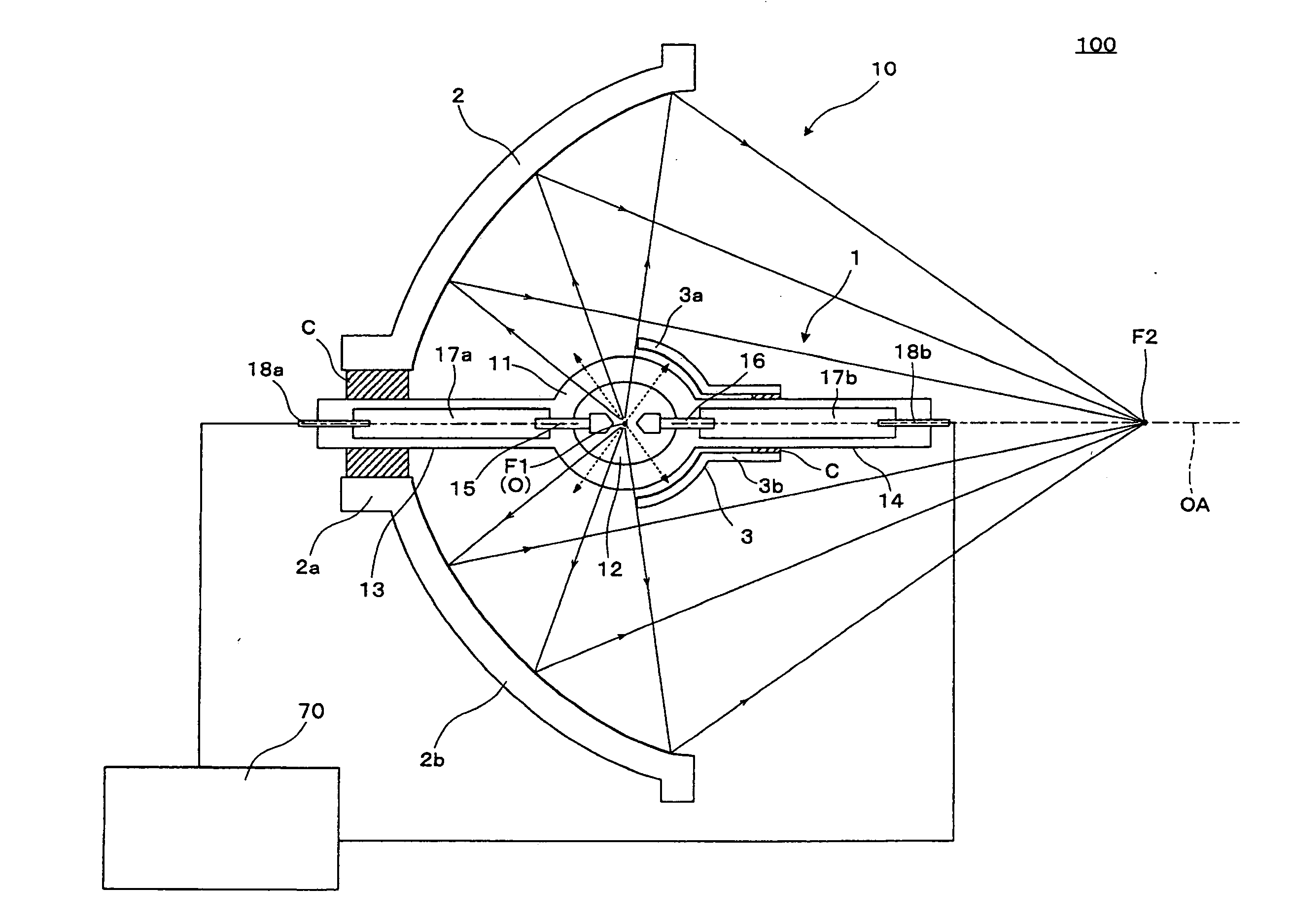
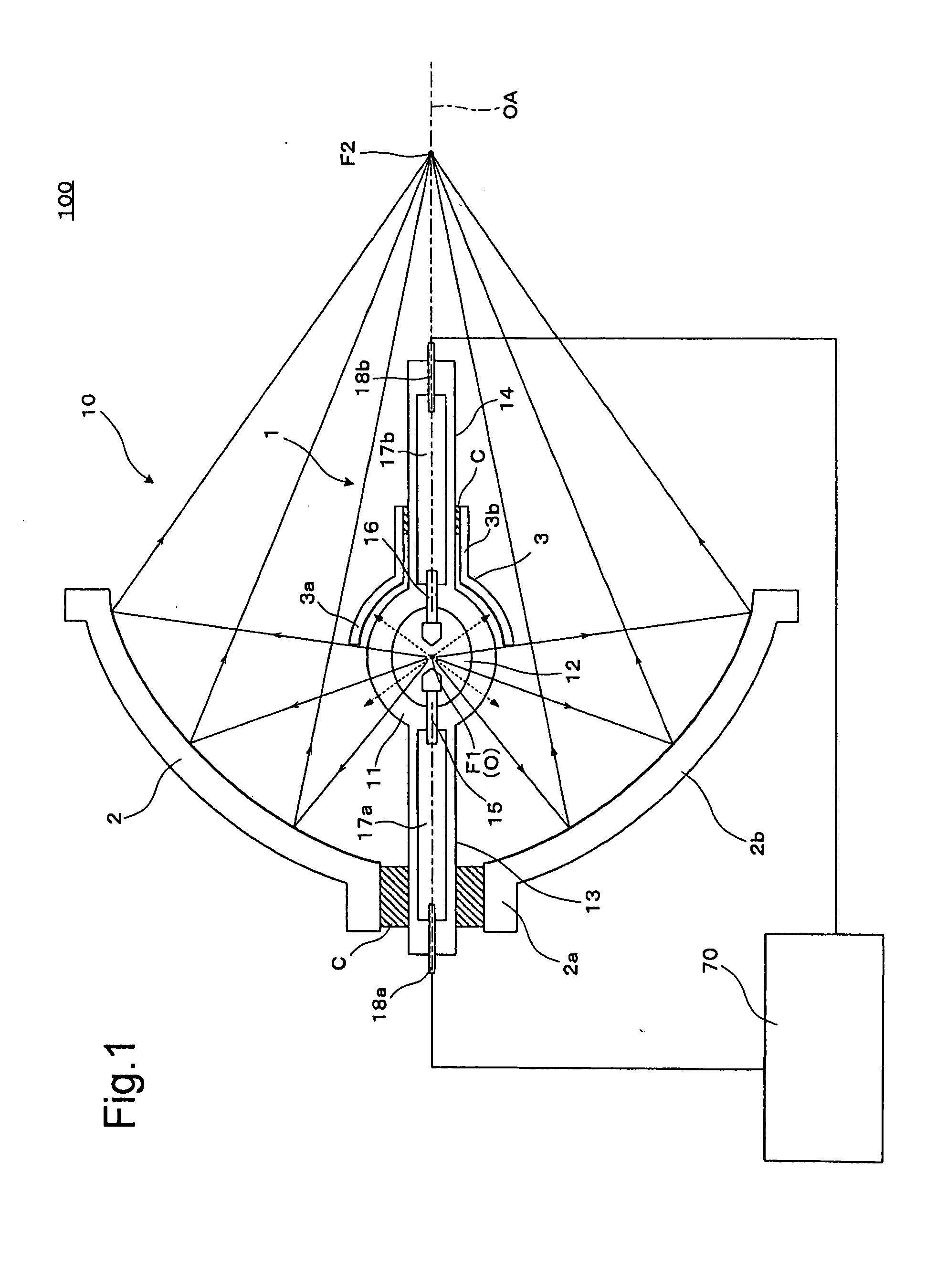
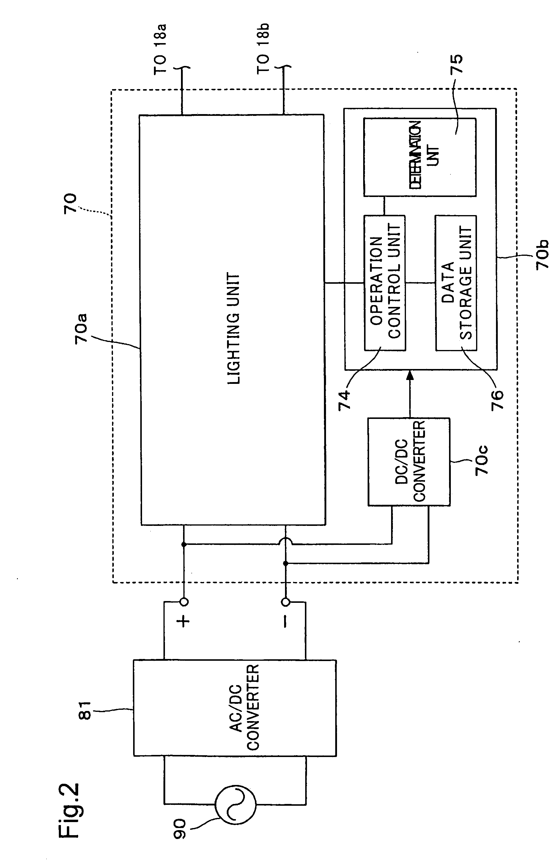
[0031]FIG. 1 is a cross section diagram showing a conceptual description of the configuration of the light source device 100. With the light source device 100, the light source unit 10 has a discharge light emission type discharge lamp 1 as a discharge lamp, a reflector 2 which is as an elliptic main reflective mirror, and a sub-mirror 3 which is a spherical reflective sub-mirror. As described in detail later, the light source driver 70 is configured as an electrical circuit for controlling light emission in the desired state by supplying alternating current to the light source unit 10.

[0032]In the light source unit 10, the discharge lamp 1 has a tube body 11 constituted by a translucent silica glass tube with the sealed center part bulged in a sphere shape. The light for illumination is emitted from the tube body 11. The discharge ...

second embodiment

[0072]Following, the light source device of the second embodiment will be described. Note that the light source device of the second embodiment is a variation of the light source device 100 of the first embodiment, and parts that are not specifically described are the same as those of the light source device 100 of the first embodiment.

[0073]FIG. 9 is a graph for describing the modulation of the duty ratio of the alternating current supplied to the pair of electrodes 15 and 16. The horizontal axis represents time, and the vertical axis represents duty ratio. With this modulation pattern of the alternating current supplied to both electrodes 15 and 16 as shown by the solid line, the section period DP1 for which the first anode duty ratio is greater than or equal to 50% where the first electrode 15 anode period is relatively long, and the section period DP2 for which the first anode duty ratio is less than or equal to 50% where the second electrode 16 anode period is relatively long a...

third embodiment

[0080]Following, the light source device of the third embodiment will be described. Note that the light source device of the third embodiment is a variation of the light source device 100 of the first embodiment, and parts not specifically described are the same as the light source device 100 of the first embodiment.

[0081]FIG. 13 is a graph for describing the modulation of the duty ratio of the alternating current supplied to the pair of electrodes 15 and 16. The horizontal axis represents time, and the vertical axis represents the duty ratio. In this case, as shown by the solid line, the modulation pattern of the alternating current supplied to both electrodes 15 and 16 consists of the anterior half period H1 for which the first anode duty ratio is greater than or equal to 50% where the anode period of the first electrode 15 is relatively long, and the posterior half period H2 for which the first anode duty ratio is less than or equal to 50% where the anode period of the second ele...


PUM


Abstract

A light source device is provided. The light source device has: a discharge lamp that emits light by discharge in an interelectrode space between a first electrode and a second electrode; a main mirror arranged at the first electrode side that reflects light flux generated by the discharge in the interelectrode space so as to emit the light flux to an area to be illuminated;a sub-mirror arranged at the second electrode side facing opposite the main mirror that reflects the light flux from the interelectrode space toward the interelectrode space; and a driver that supplies alternating current to the first and the second electrodes, and changes duty ratio of the alternating current supplied to the first and the second electrodes in accordance with a predetermined pattern. In the light source device, maximum value of time ratio of a first anode period in which the first electrode works as anode to one cycle of the alternating current is larger than maximum value of time ratio of a second anode period in which the second electrode works as anode to the one cycle of the alternating current.

Description

CROSS-REFERENCE TO RELATED APPLICATIONS[0001]The present application claims the priority based on Japanese Patent Application No. 2007-325592 filed on Dec. 18, 2007, Japanese Patent Application No. 2008-204681 filed on Aug. 7, 2008, Japanese Patent Application No. 2007-322927 filed on Dec. 14, 2007, and Japanese Patent Application No. 2008-204658 filed on Aug. 8, 2008 the disclosures of which are hereby incorporated herein by reference in its entirety.BACKGROUND OF THE INVENTION[0002]1. Field of the Invention[0003]The present invention relates to a light source device equipped with a discharge lamp that has a pair of electrodes, the driving method of such a discharge lamp, and a projector that incorporates such a discharge lamp.[0004]2. Description of the Related Art[0005]As a driving waveform for lighting a high intensity discharge lamp, a single drive waveform is used. However, when lighting with a single drive waveform continues for a long time, temperature distribution of the el...

Claims


Application Information

Patent Timeline
Patent Type & Authority Applications(United States)
IPC IPC(8): G03B21/28H05B41/14
CPCG03B21/00H05B41/2928H05B41/2883H01J61/86G03B21/005
Inventor YAMAUCHI, KENTAROTERASHIMA, TETSUOTAKEZAWA, TAKESHIOKAWA, KAZUOSOMA, SHIGEYASU
Owner SEIKO EPSON CORP
Why Eureka
Try Eureka