Frit-containing pastes for producing sintered frit patterns on glass sheets
a technology of frit-containing pastes and glass sheets, which is applied in the direction of transportation and packaging, ceramic layered products, chemistry apparatuses and processes, etc., can solve the problems of reducing the useful life of light emitting devices and prone to damage of lids, and achieve the effect of restricting the scope of invention
- Summary
- Abstract
- Description
- Claims
- Application Information
AI Technical Summary
Benefits of technology
Problems solved by technology
Method used
Image
Examples
example 1
[0058]This example illustrates the effects on surface roughness of reducing the size of the glass particles alone (see column 200 in FIG. 5), the filler particles alone (see column 300 in FIG. 5), or both the glass particles and the filler particles (see column 400 in FIG. 5).
[0059]With regard to the glass particles, it was found that by reducing the particle size, especially by removing the long tail of the particle size distribution, the surface roughness of a sintered frit pattern produced using the glass particles was improved.
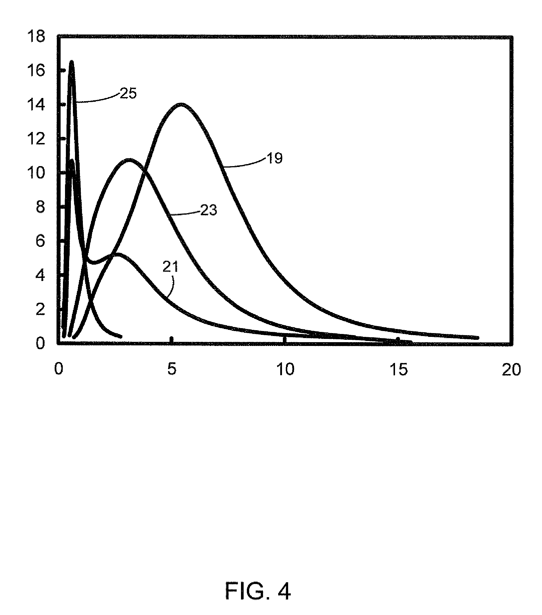
[0060]Using Fourier analysis (auto-correlation) on the topography of a sintered frit, the root mean square average (RMS) of surface roughness was found to be reduced from 2.97 microns for the glass particles of curve 21 of FIG. 4 (see column 100 of FIG. 5) to 1.67 microns for the curve 25 glass particles (see column 200 of FIG. 5).
[0061]It was also found that reducing filler particle size alone can achieve a smoother surface. When the fill...
example 2
Processing Window
[0063]This example shows that the processing window for laser sealing is much wider for pastes with smaller filler particles regardless of the sizes of the glass particles. A wider sealing window is desirable since it allows the laser sealing process to be used with a greater variety of glass sheets 12, substrates 16, and OLED constructions.
[0064]As shown in Table 1, for pastes with fillers having particles primarily in the range of 3-7 microns (see curve 19 in FIG. 4), the sealing window is about 2-3 watts wide for both 10 and 20 nm / s laser sealing speeds. Also, the highest seal width (i.e., percentage of original pre-sintered width) is about 80%. With further increase of laser power, a laser track (i.e., voids along the sintered frit line after exposure to the laser beam) starts to show up, which is not desirable.
[0065]However, for pastes with small filler particles (median shifted by approximately −3 microns; see curve 23 in FIG. 4), the sealing window is about 7...
example 3
Package Strength
[0066]FIG. 6 illustrates that pastes with smaller fillers show higher mechanical strength.
[0067]The seal width in this case was about 88%. For this width, the frits with small filler particles (curve 23 in FIG. 4; circular data points in FIG. 6) was stronger than those with larger filler particles (curve 19 in FIG. 4; diamond data points in FIG. 6). The characteristic load, S0, was 40.3 lbf for the large filler paste, and 46.9 lbf for the small filler one. The improvement of the small filler paste is thus about 15%. As can be seen in FIG. 6, other than for 6 samples, the strength of the 28 samples tested was higher than 40 lbf.
PUM
| Property | Measurement | Unit |
|---|---|---|
| Length | aaaaa | aaaaa |
| Length | aaaaa | aaaaa |
| Length | aaaaa | aaaaa |
Abstract
Description
Claims
Application Information
 - R&D
- Intellectual Property
- Life Sciences
- Materials
- Tech Scout
- Unparalleled Data Quality
- Higher Quality Content
- 60% Fewer Hallucinations
Browse by: Latest US Patents, China's latest patents, Technical Efficacy Thesaurus, Application Domain, Technology Topic, Popular Technical Reports.
© 2025 PatSnap. All rights reserved.Legal|Privacy policy|Modern Slavery Act Transparency Statement|Sitemap|About US| Contact US: help@patsnap.com


