Power supply system

a power supply system and power supply technology, applied in the direction of current conducting connection, cell components, safety/protection circuit, etc., can solve the problems of increasing the cost and weight of the battery assembly, the terminals of the batteries at the end of the rows are misaligned, and the length of each individual battery cell is too long, so as to achieve convenient stacked, low voltage, and the effect of a larger battery

Inactive Publication Date: 2009-06-18
FORD GLOBAL TECH LLC
View PDF63 Cites 87 Cited by
  • Summary
  • Abstract
  • Description
  • Claims
  • Application Information

AI Technical Summary

Benefits of technology

[0012]One advantage of the present invention is that it allows cylindrical battery cells to be pre-assembled in relatively small, rectangular packages, which are easily stacked and otherwise fit together to make a larger battery.
[0013]Another advantage of the present invention is that the small packages of cells can each be made relatively low voltage, which increases safety. Moreover, higher voltage devices may require an insulating wrap, which is not necessary with embodiments of the present invention.
[0014]The present invention provides a power supply system in which individual battery cells can be connected in rows in an end-to-end fashion to form a battery module. A number of these battery modules can be placed into a housing, to form a “brick”, which is a basic building block that can be used to create a larger battery assembly. In order to eliminate the problem of tolerance stack up with regard to adjacent battery modules, the brick can be formed in such a way as to include a locating device for some or all of the battery cells within a battery module. The locating devices can be appropriately spaced such that the variation in length of a battery module is minimized. This helps to ensure that the terminals disposed at the ends of each battery module are positioned at an appropriate distance from the end of the brick so they can be easily connected to adjacent modules within the same brick or an adjacent brick.
[0015]The invention also provides a system for electrically connecting a large number of modules together to provide a high voltage output, wherein service personnel are exposed to only a small fraction of the overall output voltage. The present invention uses terminal connectors, or interconnects, which, in addition to connecting adjacent cells or modules to each other, also cover the electrical connection of another se

Problems solved by technology

Their cylindrical shape does, however, create a number of challenges when they are combined in large quantities to create a high voltage battery.
For example, the individual battery cells need to be electrically connected to each other, which can create a large number of electrical connections adding cost and weight to the battery assembly.
Moreover, the individual battery cells are usually grouped together in various arrangements that are heavy and unwieldy, and may require lift assist devices to move them.
One problem with this approach is that each individual battery cell has a length that is subject to a manufacturing tolerance.
This problem, caused by tolerance stack up, can lead to misalignment of the terminals of the batteries at the ends of the rows.
In addition to variations in the length of the battery cells, the tolerance stack up problem can be exacerbated by differences in the sizes of any interconnecting components.
Thus, it may be difficult to connect two adjacent rows of batteries to each other if one of the rows is significantly longer than the other.
Such uniform contact can be difficult o

Method used


Image

  • Power supply system
  • Power supply system
  • Power supply system

Examples


Embodiment Construction

)

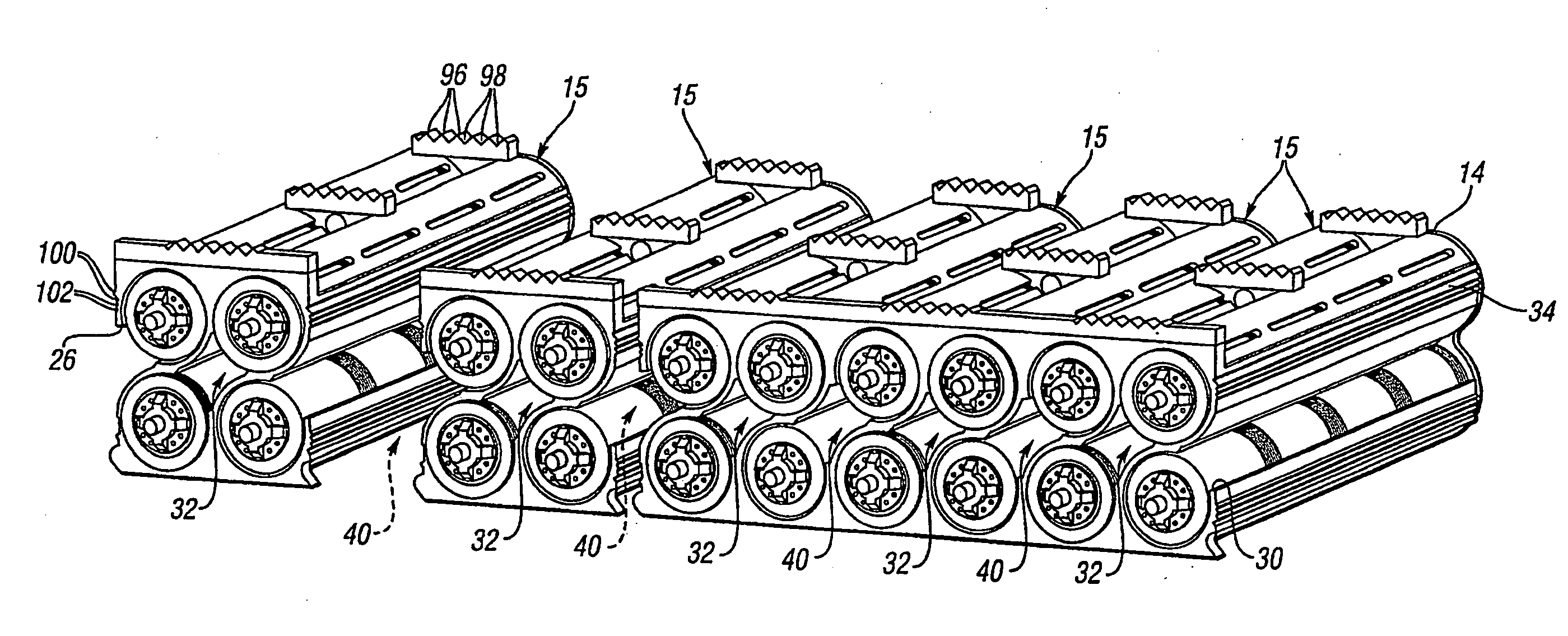
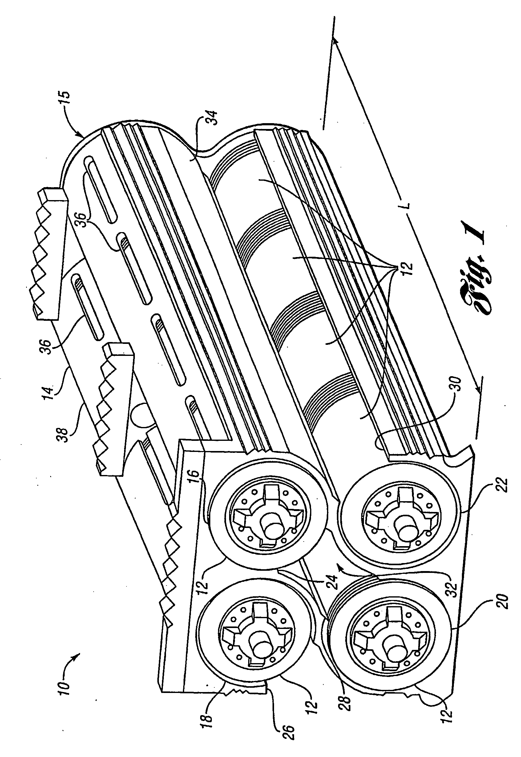
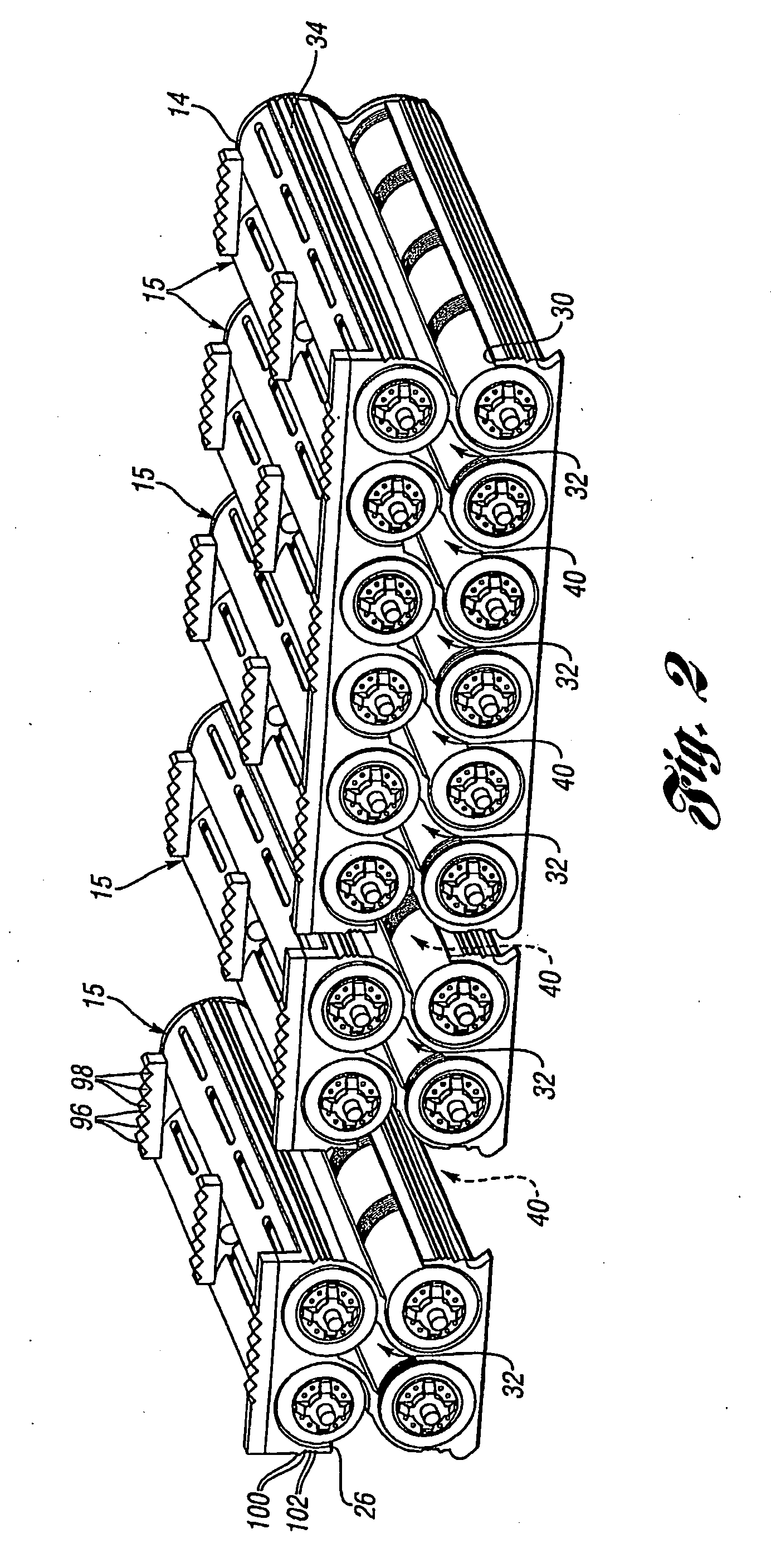
[0050]FIG. 1 shows a power supply system 10 in accordance with one embodiment of the present invention. The power supply system includes a plurality of power supply units, or battery cells 12, arranged in a housing 14, thereby forming a brick 15. As shown in FIG. 1, the battery cells 12 are generally cylindrical, having a generally circular cross section. The housing 14 includes four generally tubular compartments 16, 18, 20, 22 configured to receive the battery cells 12.

[0051]As shown in FIG. 1, each of the compartments 16, 18, 20, 22 is arranged to receive four of the battery cells 12 configured in an end-to-end configuration. For convenience, a group of the battery cells 12 disposed in an end-to-end configuration may be conveniently referred to as a module. Although the housing 14 shown in FIG. 1 is configured to receive four battery modules, for a total of 16 of the battery cells 12, it is understood that the present invention includes housings capable of receiving a greater nu...


PUM


Abstract

A power supply system includes a number of battery cells connected in rows in an end-to-end fashion to form a battery module. A number of these battery modules are placed into a housing to form a battery brick, which is a basic building block that can be used to create a larger battery assembly. The power supply system may include locators to position individual battery cells within a row, to help ensure proper alignment of battery terminals extending outside the battery housing. Terminal connectors can be used to reduce the magnitude of the voltage seen across exposed terminals. The terminal connectors connect two of the battery terminals, while covering, and inhibiting access to, adjacent battery terminals. The power supply system may also include sensor stations to facilitate use of temperature sensors such that uniformity of airflow around the battery cells is maintained regardless of how many temperature sensors are used.

Description

CROSS-REFERENCE TO RELATED APPLICATIONS[0001]This application claims the benefit of U.S. Provisional Application Ser. No. 60 / 662,418, filed Mar. 16, 2005, which is hereby incorporated herein by reference.BACKGROUND OF THE INVENTION[0002]1. Field of the Invention[0003]The present invention relates to a power supply system, and more particularly, a power supply system that can be used, for example, in conjunction with a hybrid electric vehicle.[0004]2. Background Art[0005]Cylindrical battery cells, which are used in a variety of applications, have standardized sizes, are relatively inexpensive, and are commonly available. All of these qualities make them good candidates for mass production high voltage batteries. Their cylindrical shape does, however, create a number of challenges when they are combined in large quantities to create a high voltage battery. For example, the individual battery cells need to be electrically connected to each other, which can create a large number of elec...

Claims


Application Information

Patent Timeline
IPC IPC(8): H01M2/24H01M50/529H01M50/213H01M50/244H01M50/249H01M50/264H01M50/291H01M50/296H01M50/502H01M50/507H01M50/51H01M50/516H01M50/517
CPCH01M2/1077H01M2/202H01M2/206H01M10/482H01M10/486H01M10/5004H02J7/0045H01M10/5016H01M10/503H01M10/5067H01M10/5073H02J7/0029H02J7/0031H01M10/5008H01M10/625H01M10/6563H01M10/643H01M10/617H01M10/6566H01M10/613Y02E60/10H01M50/51H01M50/507H01M50/213H01M50/264H01M50/516H02J7/00H01M50/50
Inventor MAGUIRE, PATRICKZHU, DOUGLASPATEL, DHARMENDRAGONZALES, PHILIPPARAMASIVAM, SARAVANAN
Owner FORD GLOBAL TECH LLC
Why Eureka
Try Eureka