
Method of replacing insulators on a tower and insulator support and transport assembly therefor

Active Publication Date: 2009-06-25
QUANTA ASSOC
View PDF23 Cites 3 Cited by
  • Summary
  • Abstract
  • Description
  • Claims
  • Application Information

AI Technical Summary

Benefits of technology

[0005]It is, therefore, a primary object of the present invention to provide a novel and improved insulator support and transport assembly which can be safely handled and used on a lattice-type tower by linemen emplaced on the tower by a helicopter.
[0006]It is also an object of the present invention to provide a novel and improved insulator support and transport assembly which is sufficiently lightweight that it can be hand positioned by a lineman on a lattice-type tower yet sufficiently strong to support a heavy electrical insulator.
[0007]It is another object of the present invention to provide a novel and improved insulator support and transport assembly which includes means for transporting an electrical insulator along a lattice-type tower from a location under the tower bridge or arms from which a damaged insulator is removed to a location accessible via helicopter where the damaged insulator can be removed from the tower and a replacement insulator delivered to the tower.
[0008]It is yet another object of the present invention to provide a novel and improved insulator support assembly for safely cradling an electrical insulator during movement along the tower and during transport to and from the tower via helicopter.
[0009]It is still another object of the present invention to provide a novel and improved insulator support assembly which includes means allowing easy loading and unloading of electrical insulators by linemen on a tower.
[0012]In still another aspect of the present invention, the insulator comprises a string of vertically aligned individual insulators, each individual insulator having at least a larger diameter skirt and a concentric smaller diameter shank extending upwardly therefrom, the cradling means comprises a partially peripherally enclosed, open-topped structure having a floor, an upstanding rear wall, peripheral walls sloping downwardly from the rear wall to a front wall, an opening in the front wall, an elongate slot in the floor extending rearwardly from the opening in the front wall at least half the distance toward the rear wall, the slot having a width greater than the diameter of the insulator shank but less than the diameter of the insulator skirt, the shape and dimensions of the floor allowing an insulator skirt to lie flat thereon within the peripheral walls of the cradling means, whereby an insulator shank can be inserted through the opening in the front wall into the slot with the insulator skirt vertically above the shank passing above the front wall, and the insulator skirt above the shank lying flat on the floor behind the front wall when the insulator is fully inserted into the cradling means, the front wall preventing the insulator from sliding out of the cradling means.

Problems solved by technology

Periodically, it is necessary to replace the insulators because they are visibly damaged or as part of a general maintenance plan.
It will be appreciated that high voltage electrical insulators are extremely heavy, e.g., about 200 pounds, and their weight makes them too difficult to be safely handled by linemen on the tower, particularly when it is appreciated that these linemen are standing on narrow girders.
Unfortunately, a helicopter does not have access to the undersides of the tower bridge or tower arms from which the insulators are supported, making it difficult to work with the helicopter without the linemen physically dragging each damaged and replacement insulator along the tower to or from a location which the helicopter can access.

Method used


Image

  • Method of replacing insulators on a tower and insulator support and transport assembly therefor
  • Method of replacing insulators on a tower and insulator support and transport assembly therefor
  • Method of replacing insulators on a tower and insulator support and transport assembly therefor

Examples


Embodiment Construction

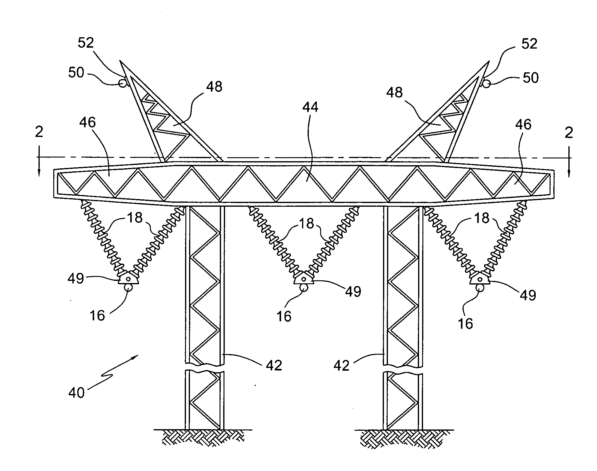
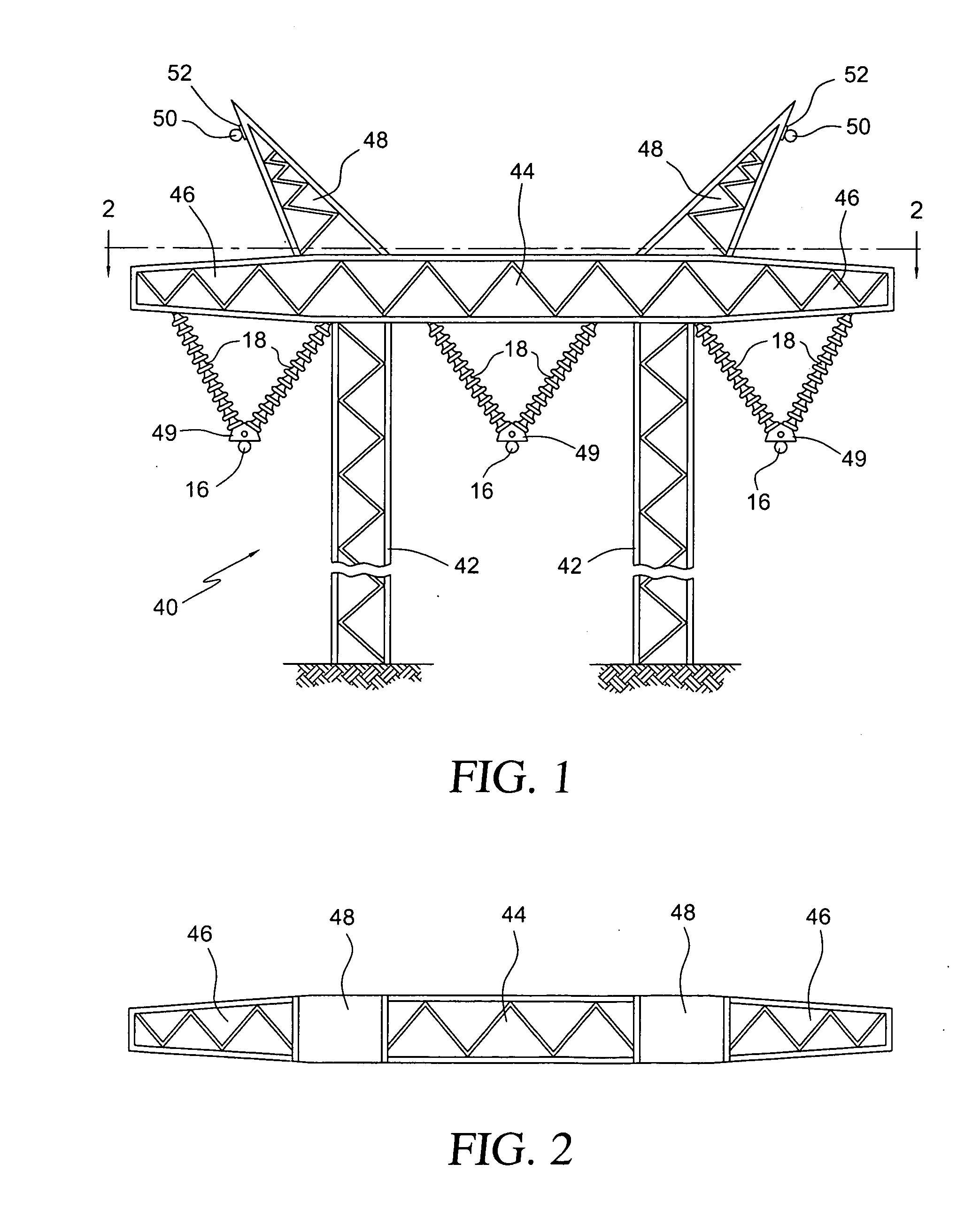
[0025]Referring to FIGS. 1 and 2 there is shown a conventional steel lattice H-structure tower 40 for supporting multiple (frequently three) high voltage conductors 16. The lattice tower 40 comprises two legs 42 extending to the ground which support a central bridge 44 having left and right side extending tower arms 46. In addition, a pair of goat heads 48 extend upwardly and outwardly at an acute angle from the bridge 44 for supporting shield wires 50 via shield wire hardware 52. The lattice structure is typically constructed of angle stock. Central bridge structure 44 comprises an elongate rectangular box formed of angled stock girders, which gives the bridge a width as well as a depth. Left and right side extending tower arms 46 also comprise elongate boxes formed of angled stock girders except, as can be seen in FIGS. 1 and 2 respectively, the girders forming the tower arms 46 incline toward each other in both the vertical and horizontal planes. Conductors 16 are supported under...


PUM

PropertyMeasurementUnit
Lengthaaaaaaaaaa
Diameteraaaaaaaaaa

Abstract

A method of replacing an electrical insulator on a conductor-supporting tower includes the steps of providing an elongate beam spanning the tower between a work site and a helicopter accessible site, a trolley movable on the beam between the sites and an insulator cradle detachably supported by the trolley for supporting the insulator during transport between the sites and to and from the tower via helicopter. The cradle is a partially peripherally enclosed, open-topped structure having a floor, an upstanding rear wall, peripheral walls sloping downwardly from the rear wall to a front wall, an opening in the front wall, an elongate slot in the floor extending rearwardly from the opening, the slot having a width greater than the diameter of an insulator shank but less than the diameter of an insulator skirt, the dimensions of the floor allowing an insulator skirt to lie flat thereon.

Description

FIELD OF THE INVENTION[0001]The present invention relates to support and transport devices for high voltage electrical insulators and, more particularly, to an insulator trolley and cradle which is particularly suitable for supporting and transporting insulators during insulator replacement on lattice-type towers.BACKGROUND OF THE INVENTION[0002]High voltage power transmission lines carrying voltages in the hundreds of kilowatt range have been constructed to extend from spaced towers or poles in terrain which is often practically inaccessible to land vehicles. In recent years, a number of methods and devices have been developed to facilitate the repair and maintenance of high voltage power transmission lines which are accessed by helicopter.[0003]Lattice-type towers are employed for supporting multiple high voltage electrical conductors. The conductors are typically supported under the arms or bridges of such towers using a pair of suspension insulators per conductor. Periodically, ...

Claims


Application Information

Patent Timeline
IPC IPC(8): B23P19/04B23P6/00
CPCY10T29/49721Y10T29/53543Y10T29/49732Y10T29/53539Y10T29/49734Y10T29/53548Y10T29/53265H02G1/02Y10T29/4973
Inventor GRAHAM, LARRY
Owner QUANTA ASSOC
Features
  • Generate Ideas
  • Intellectual Property
  • Life Sciences
  • Materials
  • Tech Scout
  • Unparalleled Data Quality
  • Higher Quality Content
  • 60% Fewer Hallucinations
Learn More