Gas safety device and the control method of heating ventilating and air conditioning system

Inactive Publication Date: 2009-06-25
METACHEM
View PDF2 Cites 0 Cited by
  • Summary
  • Abstract
  • Description
  • Claims
  • Application Information

AI Technical Summary

Benefits of technology

[0019]The present invention provides a gas safety device of a heating, ventilating, and air conditioning system for vehicles, in which when a signal value from either a gas sensor installed at an air inlet connecting an engine room and the inside of a vehicle or a shock sensor installed in the vehicle is input to a control unit, the control unit determines whether or not gas is leaked through the input signal value, selectively operates a refrigerant cutoff valve installed at a line of an evaporator at the side of a refrigerant inlet, an

Problems solved by technology

In order to liquefy the refrigerant, which is changed into a gas state by absorbing heat from the evaporator, again, the refrigerant must be decreased to a temperature of −29.

Method used


Image

  • Gas safety device and the control method of heating ventilating and air conditioning system
  • Gas safety device and the control method of heating ventilating and air conditioning system

Examples


first embodiment

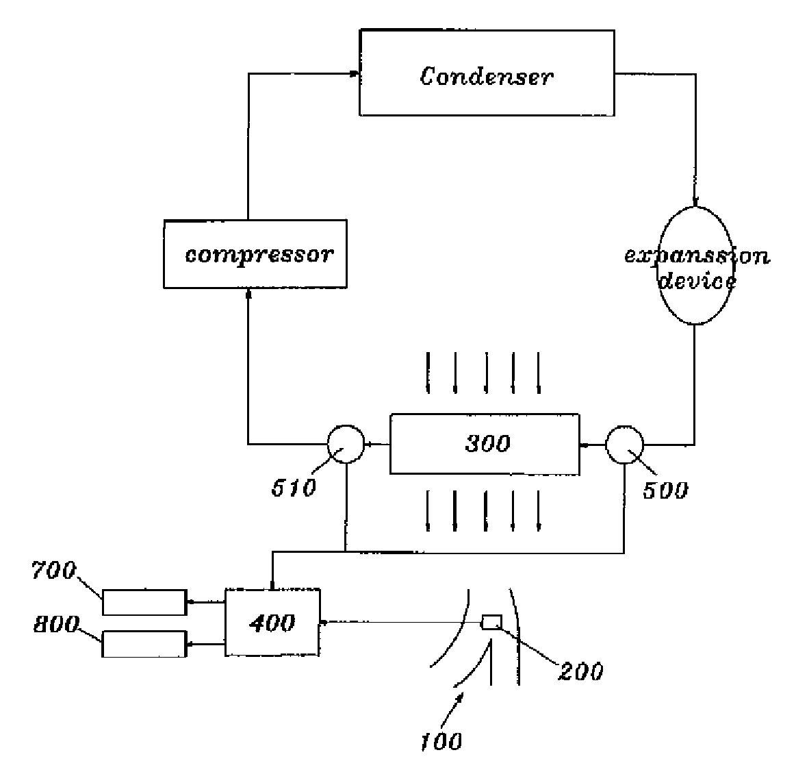
[0026]As shown in FIG. 1, a gas safety device of a heating, ventilating, and air conditioning system for vehicles in accordance with a first embodiment of the present invention includes a gas sensor 200, which is installed at an air inlet 100 connecting an engine room and the inside of a vehicle and senses a gas leakage, and refrigerant cutoff valves 500 and 510, which are installed at lines of an evaporator 300 at the sides of refrigerant inlet and outlet and restrict the flow of a refrigerant according to a signal value through a control unit 400.

[0027]The gas sensor 200 is installed in a passage of the air inlet 100 connecting the engine room and the inside of the vehicle, senses gas flowing in together with air, and outputs a corresponding signal value to the control unit 400.

[0028]The gas sensor 200 contains a combustible refrigerant or a non-combustible refrigerant, which is used as a refrigerant gas for vehicles. Here, R-152a may be used as the combustible refrigerant.

[0029]T...

second embodiment

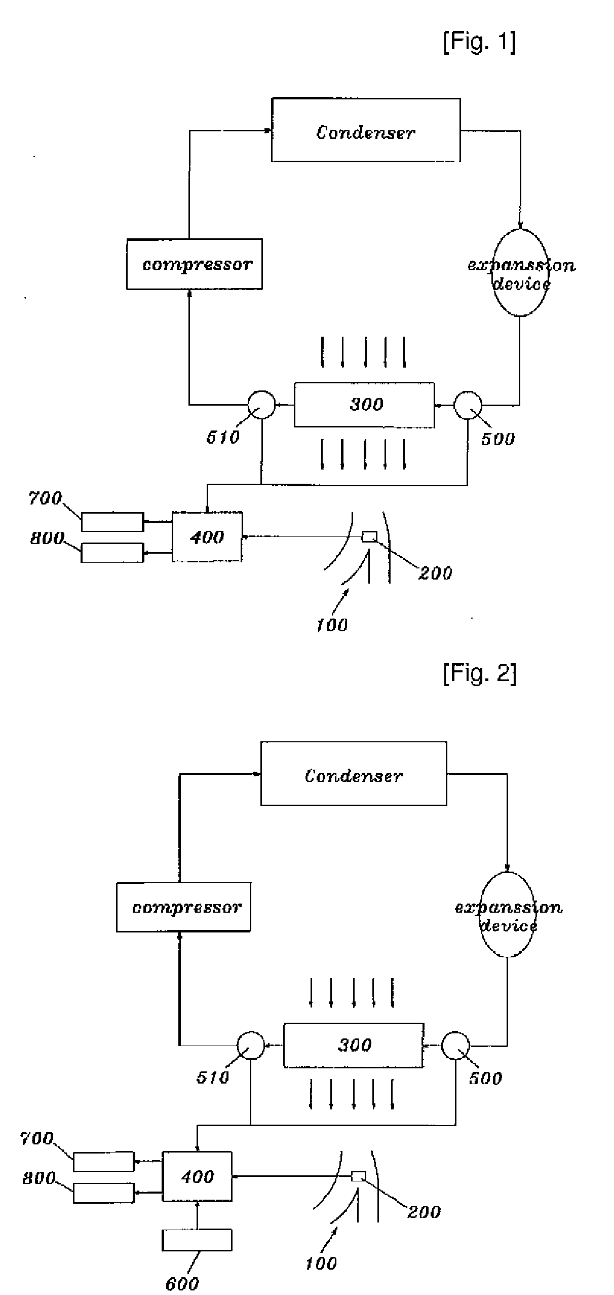
[0032]As shown in FIG. 2, a gas safety device of a heating, ventilating, and air conditioning system for vehicles in accordance with a second embodiment of the present invention includes a gas sensor 200, which is installed at an air inlet 100 connecting an engine room and the inside of a vehicle and senses a gas leakage, a shock sensor 600, which is installed in the vehicle and senses a shock when the shock is applied to the vehicle, and refrigerant cutoff valves 500 and 510, which are installed at lines of an evaporator 300 at the sides of refrigerant inlet and outlet and restrict the flow of a refrigerant according to a signal value through a control unit 400.

[0033]The gas sensor 200 is installed in a passage of the air inlet 100 connecting the engine room and the inside of the vehicle, senses gas flowing in together with air, and outputs a corresponding signal value to the control unit 400.

[0034]The gas sensor 200 contains a combustible refrigerant or a non-combustible refrigera...


PUM


Abstract

Disclosed is a gas safety device of a heating, ventilating, and air conditioning system for vehicles. The gas safety device includes a gas sensor installed at an air inlet connecting an engine room and the inside of a vehicle; and refrigerant cutoff valves installed at lines of an evaporator at the sides of refrigerant inlet or outlet for restricting the flow of a refrigerant by means of the operation of a control unit according to a sensing signal value of the gas sensor. In the gas safety device, when gas is leaked in the engine room after a starting switch of the vehicle is turned on, the gas sensor installed at the air inlet connecting the engine room and the inside of the vehicle senses the gas leakage, and outputs a corresponding signal value to the control unit. Then, the control unit determines whether or not gas is leaked through the signal value, and operates the refrigerant cutoff valve installed at the line of the evaporator at the side of the refrigerant inlet, thus controlling the flow of the refrigerant.

Description

TECHNICAL FIELD[0001]The present invention relates to a gas safety device of a heating, ventilating, and air conditioning system for vehicles, and more particularly to a gas safety device of a heating, ventilating, and air conditioning system for vehicles, which senses gas leaked from an evaporator of a vehicle and cuts off the gas leakage so as to safely protect passengers in the vehicle.BACKGROUND ART[0002]In general, heating, ventilating, and air conditioning (hereinafter, referred to as “HVAC”) systems for vehicles are applied to a vehicle so as to allow passengers in the vehicle to enjoy a drive in a comfortable state through cooling or heating. Techniques of HVAC systems had been rapidly developed, and an HVAC system, which is controlled by itself without a driver's separate manipulation and adjusts an indoor temperature to a setting value according to a variation of external heat, has been developed now.[0003]Such a HVAC system is an apparatus for controlling indoor air in a ...

Claims


Application Information

Patent Timeline
IPC IPC(8): F25D3/00F25D29/00B60H1/32
CPCB60H1/00978B60H1/3225B60H1/3217B60H1/00985G05D21/00
Inventor LEE, DEOK-JAE
Owner METACHEM
Why Eureka
Try Eureka