Pneumatic tire manufacturing method and pneumatic tire

a pneumatic tire and manufacturing method technology, applied in mechanical equipment, transportation and packaging, other domestic objects, etc., can solve the problems of deterioration of uniformity, reducing productivity, and low workability, and achieve the effect of improving productivity, reducing uniformity, and easy attachmen

Active Publication Date: 2009-06-25
YOKOHAMA RUBBER CO LTD
View PDF7 Cites 22 Cited by
  • Summary
  • Abstract
  • Description
  • Claims
  • Application Information

AI Technical Summary

Benefits of technology

[0012]The present invention is capable of avoiding falling off of the two-side fasteners from the inner circumferential surface of the first formed body while the first formed body is being deformed into the toroidal shape by expansion. That is because the present invention described above causes the first formed body to be made by intermittently attaching the two-side fasteners to the inner circumferential surface of the first formed body. Thus, the intermittent portions of the first formed body between the neighboring two-side fasteners are allowed to be stretched by following the expanding deformation of the first formed body into the toroidal shape while not obstructed by the two-side fasteners, when the first formed body is thus deformed.
[0013]Consequently, the present invention makes it possible to attach the two-side fasteners to the inner circumferential surface of the first formed body on the making drum. This makes it easy to attach the two-side fasteners thereto, and makes it possible to enhance the productivity. Concurrently, this makes it possible to easily attach the two-side fasteners to the predetermined locations on th...

Problems solved by technology

The attachment requires meticulous work and results in a lower workability.
This is a cause of decreasing the productivity.
This manual work makes it difficult to attach the surface fasteners to the inner surface around an entir...

Method used


Image

  • Pneumatic tire manufacturing method and pneumatic tire
  • Pneumatic tire manufacturing method and pneumatic tire
  • Pneumatic tire manufacturing method and pneumatic tire

Examples


first embodiment

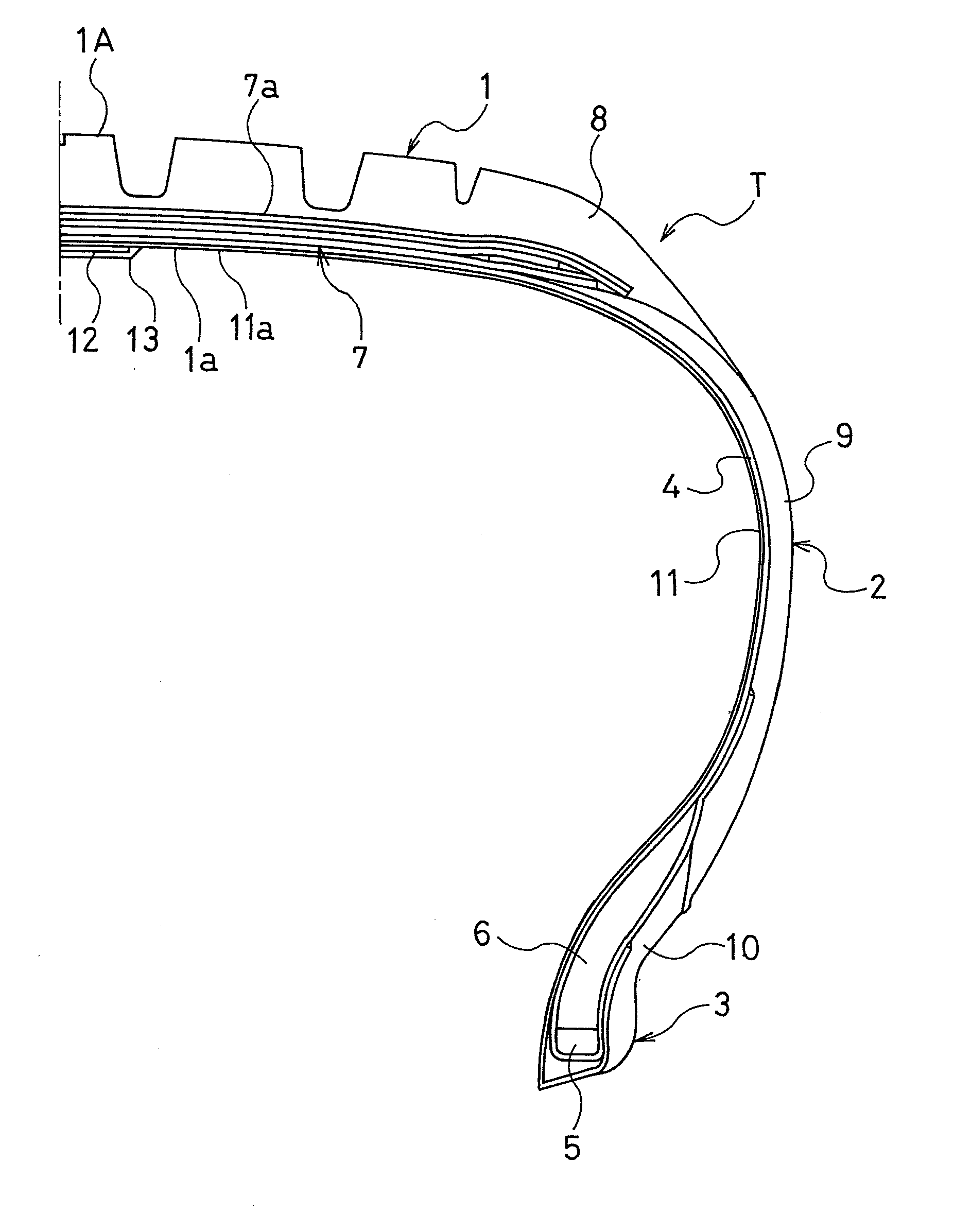
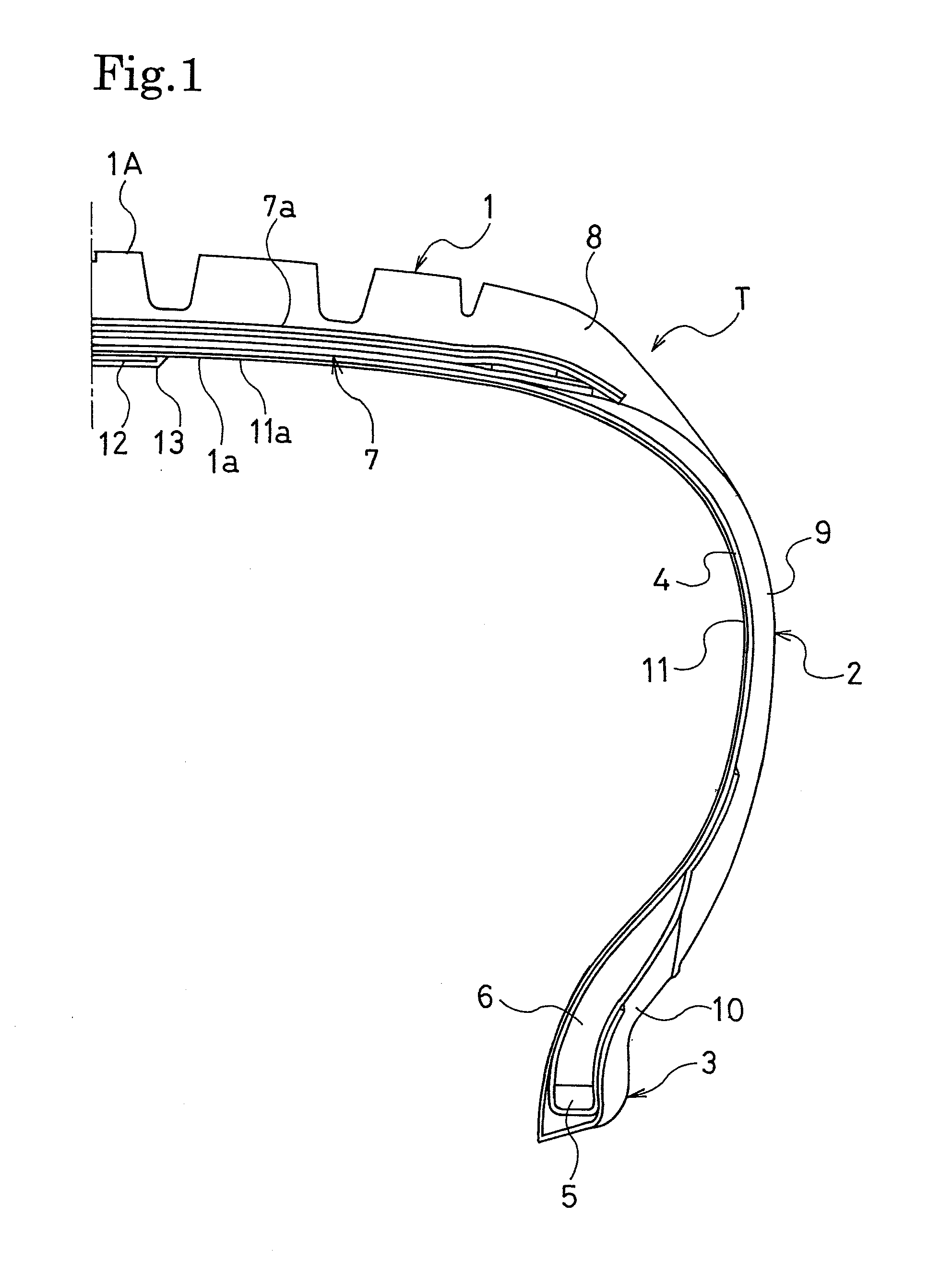
[0049]Descriptions will be provided hereinbelow for a method of manufacturing the pneumatic tire T configured as shown in FIG. 1 by use of the pneumatic tire manufacturing method according to the present invention by referring to FIGS. 4 to 7.

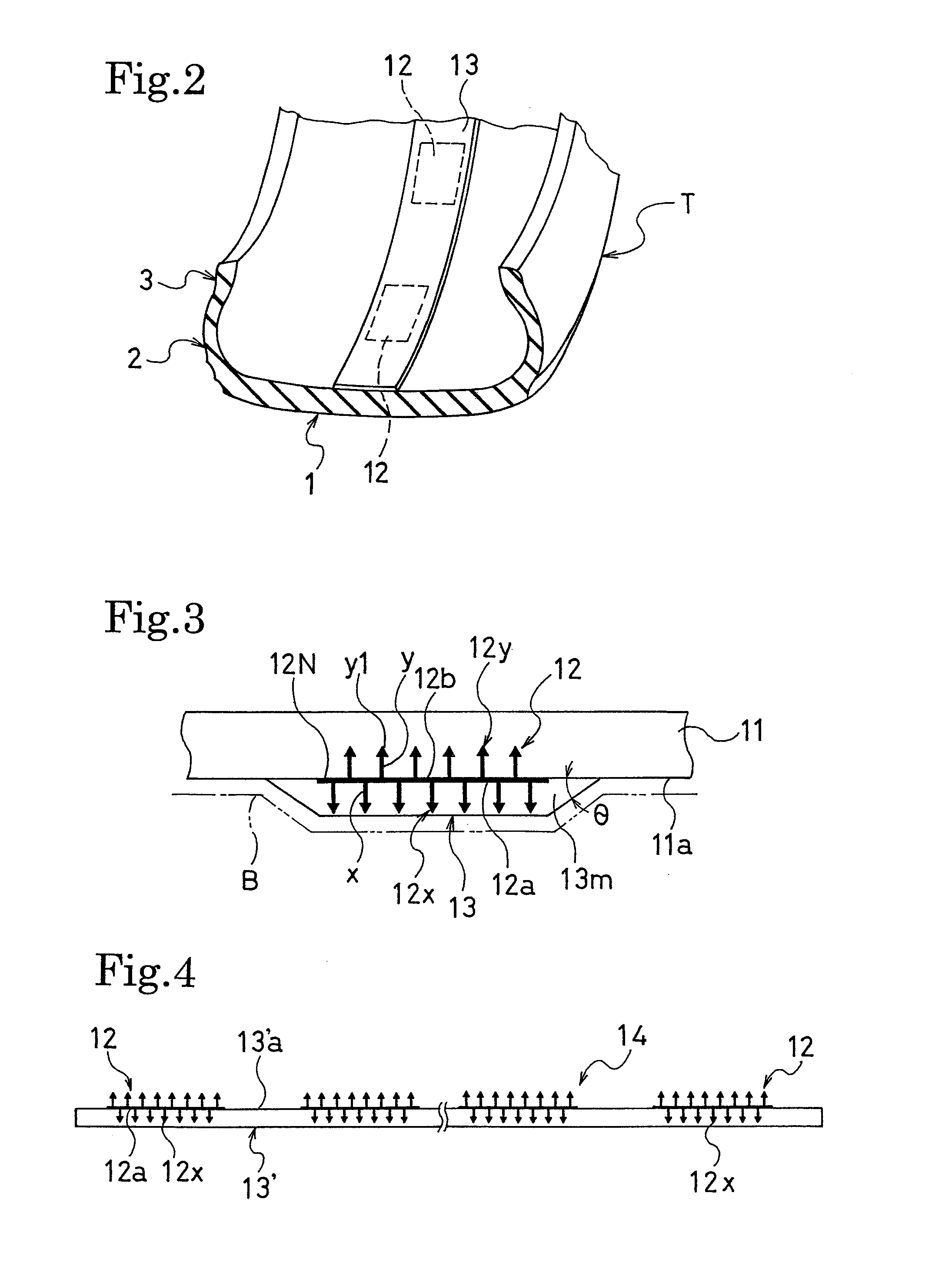
[0050]First of all, as shown in FIG. 4, multiple two-side fasteners 12 are intermittently attached to a first side 13′a of a belt-shaped protective rubber layer 13′ made of an uncured rubber at predetermined intervals in the longitudinal direction of the protective rubber layer 13′ in a way that the engagement element group 12x on the first side 12a of each two-side fastener 12 is buried in the first side 13′a of the protective rubber sheet 13′. Thereby, a protective rubber layer 14 with the two-side fasteners is formed.

[0051]It is desirable that the length of each two-side fastener 12 should be as short as possible in the longitudinal direction of the protective rubber layer as long as the length of the two-side fastener is long enough for its...

second embodiment

[0063]FIGS. 9 to 11 show the pneumatic tire manufacturing method according to the present invention. As shown in FIG. 9, this manufacturing method causes a protective rubber layer 14 with a two-side fastener to be made by intermittently attaching a single belt-shaped two-side fastener 12 on a first side 13′a of a single belt-shaped protective rubber layer 13′ made of an uncured rubber in a longitudinal direction of the protective rubber layer 13′ in a way that engagement element groups 12x on a first side 12a of the two-side fastener 12 are buried in the first side 13′a of the protective rubber layer 13′. In this respect, the engagement element groups 12x are arranged on the first side 12a of the two-side fastener 12 at predetermined intervals in the longitudinal direction of the two-side fastener 12, whereas engagement element groups 12y are arranged on a second side 12b of the two-side fastener 12 at predetermined intervals in the longitudinal direction thereof.

[0064]Subsequently,...

third embodiment

[0067]FIGS. 13 to 16 show the pneumatic tire manufacturing method according to the present invention. As shown in FIGS. 13 and 14, this manufacturing method causes a protective rubber layer 14 with a two-side fastener to be made by use of a single belt-shaped two-side fastener 12 as follows. Engagement element groups 12x are arranged on a first side 12a of the two-side fastener 12 at predetermined intervals in the longitudinal direction of the two-side fastener 12, whereas engagement element groups 12y are arranged on a second side 12b of the two-side fastener 12 at predetermined intervals in the longitudinal direction thereof. In addition, a cut line 16 is provided between each two neighboring engagement element groups 12x or 12y. As shown in FIG. 14, this belt-shaped two-side fastener 12 is intermittently attached onto a first side 13′a of a single belt-shaped protective rubber layer 13′ made of an uncured rubber in a longitudinal direction of the protective rubber layer 13′ in a ...


PUM

PropertyMeasurementUnit
Pressureaaaaaaaaaa
Pressureaaaaaaaaaa
Fractionaaaaaaaaaa

Abstract

Provided is a pneumatic tire manufacturing method capable of improving the productivity of pneumatic tires each having surface fasteners in its tire inner surface, and of avoiding manufacturing a pneumatic tire having a deteriorated uniformity, as well as of preventing engagement elements of each surface fastener from being crushed. Also, provided is a pneumatic tire manufactured by the pneumatic tire manufacturing method. The pneumatic tire manufacturing method according to the present invention includes the steps of, in making a green tire having two-side fasteners in its tire inner surface in its tire circumferential direction, each two-side fastener including an engagement element group on both sides: covering the engagement element groups on first sides of the two-side fasteners with a protective rubber layer made of an uncured rubber; making a cylindrical first formed body on a making drum, with the two-side fasteners covered with the protective rubber layer being intermittently attached to an inner circumferential surface of the first forming body in a circumferential direction thereof with the engagement element groups on second sides of the two-side fasteners being interposed in between; bonding the first formed body to an inner circumference of an annular second formed body by compression through expanding the first formed body into a toroidal shape, and thereby making the green tire; and curing the green tire inside a mold of a curing machine while pressing the green tire from its inside by a bladder.

Description

BACKGROUND OF THE INVENTION[0001]1. Field of the Invention[0002]The present invention relates to: a method of manufacturing a pneumatic tire having surface fasteners on its tire inner surface; and a pneumatic tire manufactured by the method. Specifically, the present invention relates to a pneumatic tire manufacturing method which improves the productivity of pneumatic tires each having surface fasteners on its tire inner surface, and which avoids manufacturing a pneumatic tire having a deteriorated uniformity, as well as which prevents engagement elements of each surface fastener from being crushed. The present invention also relates to a pneumatic tire manufactured by the manufacturing method.[0003]2. Description of the Related Art[0004]In a pneumatic tire, noise absorbing materials are provided to the inner surface of the tire cavity for the purpose of reducing cavity resonance. The applicant of the present invention has made a proposal on a pneumatic tire having surface fastener...

Claims


Application Information

Patent Timeline
IPC IPC(8): B60C9/02B29D30/00
CPCB29D30/0061B29D30/20B29D2030/0072Y10T152/10855B60C19/002Y10T152/10495B29D2030/0637
Inventor TANNO, ATSUSHIOGAWA, SHIROFUJITA, AKIRAYAMABE, TOMIO
Owner YOKOHAMA RUBBER CO LTD
Why Eureka
Try Eureka