Control method of a device for nebulizing liquids into the air

a control method and liquid technology, applied in the direction of applications, atomized substances, transportation and packaging, etc., can solve the problems of reducing the perception of odor, reducing the efficiency of continuous nebulization, and reducing the operating li

Inactive Publication Date: 2009-06-25
OSMOOZE SA
View PDF8 Cites 27 Cited by
  • Summary
  • Abstract
  • Description
  • Claims
  • Application Information

AI Technical Summary

Benefits of technology

[0036]According to an embodiment, the control unit is configured to determine the respective durations of successive idle periods in such a way as to produce “odor peaks”, taking account of human olfactory neurosensory characteristics and by providing an additional waiting time.

Problems solved by technology

These devices device can only treat volumes within a limited size range, from 40 m3 to about 170 m3, and also have a relatively limited operating life depending on the size of the aerosol canister, which can reach 6 months for the smallest volumes and 1.5 months for the largest volumes.
On the other hand, continuous nebulization gives poor efficiency.
In fact, because of the human neurosensory characteristics and particularly the phenomenon of habituation, the perception of an odor diminishes and disappears after a few minutes, unless the odor is of excessive intensity and therefore induces nausea that may be intolerable.
Generally speaking, the above-mentioned devices do not enable to reach the best olfactory yield for all possible combinations of parameters associated with olfactory efficiency, and especially the olfactory atmosphere to be created (welcome, permanent atmosphere, odor peak), and with the characteristics of the treated location (volume, function).
Nor do they allow programming spraying cycles at will depending on other criteria, including by allowing to shift from optimal olfactory efficiency, especially if the products sprayed are not perfumed.
In fact, to treat smaller volumes, the duration of the idle periods between perfume nebulizing cycles can be increased, but this risks affecting the stability of olfactory perception, especially when spraying a welcome odor in a location that is occupied on a temporary basis.
Besides, when the duration of the nebulizing cycles is less than a certain value of the order of 50 ms, it is difficult to control the flow rate of liquid thus sprayed.
On the other hand, to treat larger volumes, the duration of idle periods can be reduced, but this affects the operating life of the device with respect to its supply of liquid to be sprayed and its power supply if it is powered by a limited energy source, for example by electric batteries.
The duration of each nebulizing cycle can also be increased, which also affects the consumption by the device of liquid to be nebulized and its electricity consumption.
Finally, none of the above-mentioned devices enables the real needs of users to be met, nor can they be adapted to the place where the device is used.
In fact, their mode of operation cannot really be adapted to the tastes and olfactory sensitivity of all users.
Nor in particular can their mode of operation be adapted to the size and function of the room, nor to the ventilation conditions, or to the precise location of the device in the room.
In particular, the above-mentioned devices equally do not enable treatment of volumes smaller than 20 m3 or greater than 300 m3.
Moreover, the devices that can treat up to 300 m3 cannot be adapted to volumes less than 75 m3, and the devices suitable for volumes up to 30 m3 cannot be used to treat volumes exceeding 120 m3.

Method used


Image

  • Control method of a device for nebulizing liquids into the air
  • Control method of a device for nebulizing liquids into the air
  • Control method of a device for nebulizing liquids into the air

Examples


Embodiment Construction

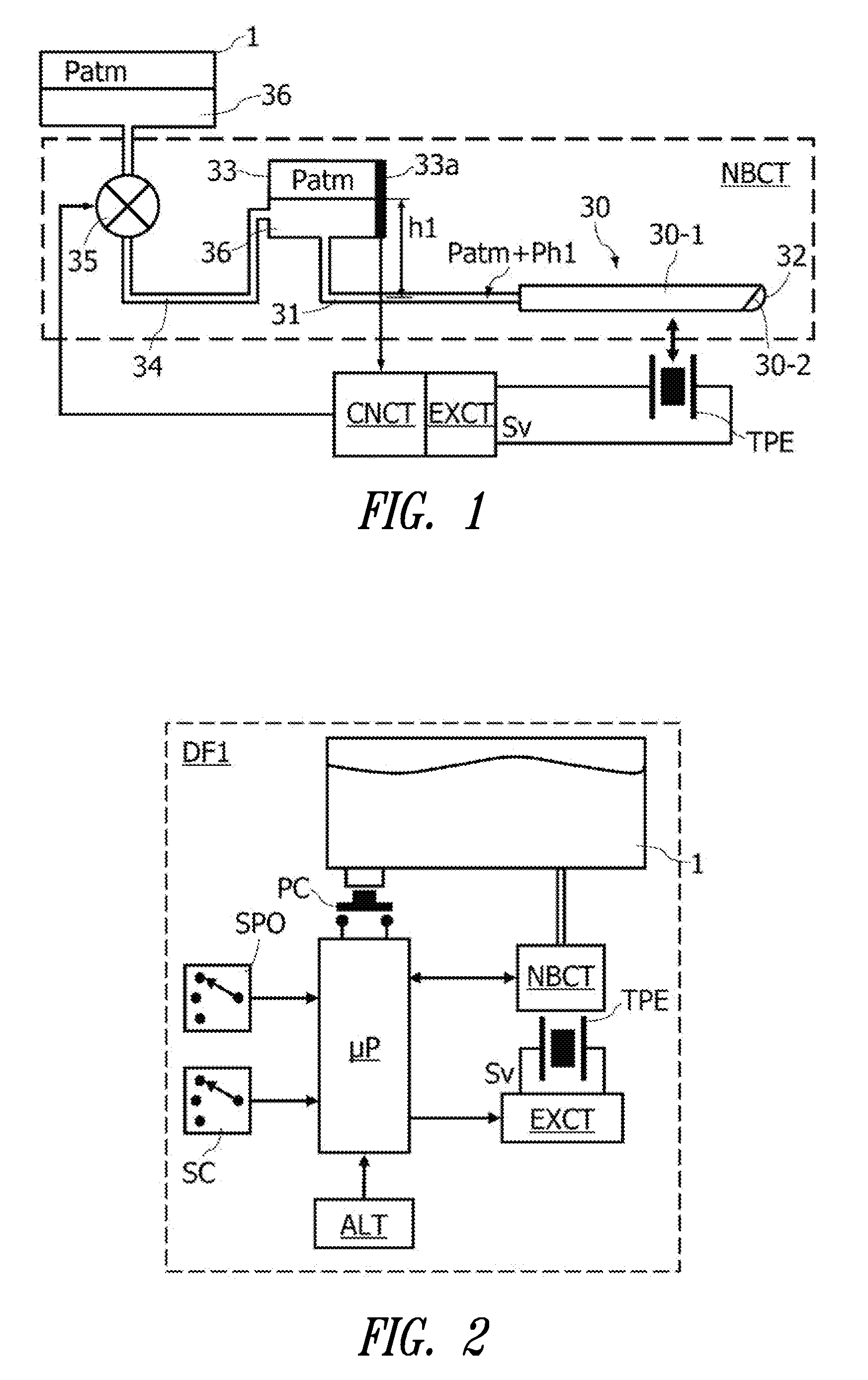
[0050]FIG. 1 represents a general diagram of a liquid nebulization device of the type having a vibrating capillary tube. The device includes a principal reservoir 1 containing a liquid 36 to be nebulized, and a nebulization circuit NBCT fed by the reservoir 1. The nebulization circuit NBCT includes a nebulization head 30, an intermediate reservoir 33 also containing liquid 36, a pipe 31 connecting the reservoir 33 to the nebulization head 30 and a pipe 34 equipped with an electric pump or valve 35, connecting reservoir 1 to reservoir 33. Reservoirs 1 and 33 are under atmospheric pressure Patm. The nebulization head 30, substantially horizontal, includes a capillary tube 30-1 and a nozzle 30-2 for liquid ejection. The nebulization head generally takes the form of a hollow needle with internal diameter less than one millimeter and a length of a few centimeters, the body of which forms the capillary tube 30-1 and the distal end of which, beveled, forms the ejection nozzle 30-2. The neb...


PUM


Abstract

A control method for one or several devices for nebulizing liquids into the air (DF1), the method including control steps for the device to nebulize a liquid into the air according to nebulizing cycles during which a liquid is nebulized into the air, the nebulizing cycles being spaced by idle periods, and comprising adjustment of the duration of idle periods as a function of the average quantity of liquid to be nebulized per unit time selected, and as a function of a concentration parameter for the active product in the liquid to be nebulized. The method enables a same apparatus to treat volumes with a factor of 100 times, typically from 7 to 700 m3.

Description

BACKGROUND[0001]1. Technical Field[0002]This disclosure concerns devices for nebulizing liquids into the air, for purposes of humidification or cooling of the air, or notably for spraying, cleaning, deodorizing, and disinfecting products, or perfumes.[0003]2. Description of the Related Art[0004]Some liquid nebulization devices include a housing for receiving an aerosol canister of the liquid to be sprayed, and a mechanism for periodically triggering release of the product in the form of an aerosol for a fixed duration. To release a liquid in the form of an aerosol, the mechanism includes an actuator to open the valve by pressing on the nozzle of the canister. Devices of this type are sold under the trademarks Microburst 3000® and Microburst 9000®. These devices device can only treat volumes within a limited size range, from 40 m3 to about 170 m3, and also have a relatively limited operating life depending on the size of the aerosol canister, which can reach 6 months for the smallest...

Claims


Application Information

Patent Timeline
Patent Type & Authority Applications(United States)
IPC IPC(8): B05B17/04
CPCA61L9/14B65D2203/10B05B17/0676B05B17/0607H04L67/12
Inventor MILLET, JEAN-CLAUDE
Owner OSMOOZE SA
Why Eureka
Try Eureka