Image sensing device

a technology of image sensing and image, which is applied in the field of image sensing devices, can solve the problems of user burden and time constraints, and achieve the effect of reducing the burden on the user

Inactive Publication Date: 2012-11-29
SANYO ELECTRIC CO LTD
View PDF2 Cites 14 Cited by
  • Summary
  • Abstract
  • Description
  • Claims
  • Application Information

AI Technical Summary

Problems solved by technology

However, this type of method is likely to place a greater burden (such as time constraint) on a user.

Method used


Image

  • Image sensing device
  • Image sensing device
  • Image sensing device

Examples


first embodiment

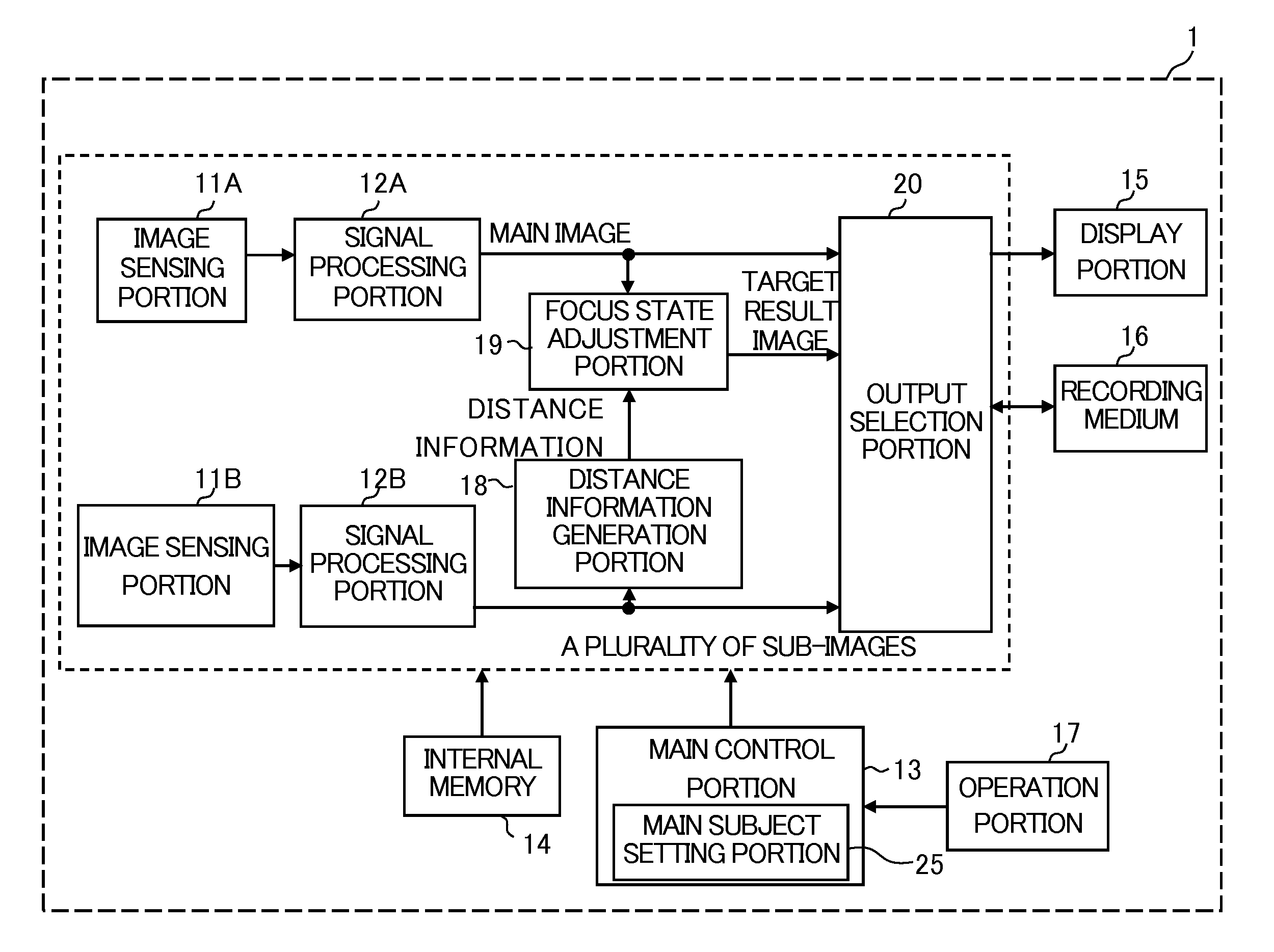
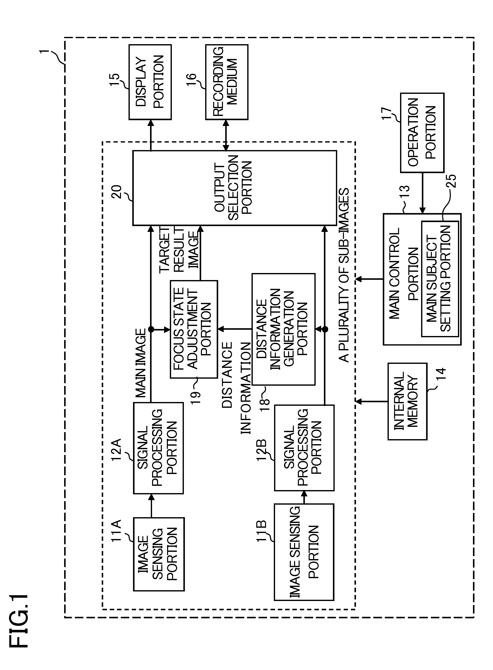
[0021]A first embodiment of the present invention will be described. FIG. 1 is a schematic overall block diagram of an image sensing device 1 according to the first embodiment of the present invention. The image sensing device 1 is a digital video camera that can shoot and record a still image and a moving image. The image sensing device 1 may be a digital still camera that can shoot and record only a still image. The image sensing device 1 may be incorporated in a mobile terminal such as a mobile telephone.

[0022]The image sensing device 1 includes a first processing unit composed of an image sensing portion 11A and a signal processing portion 12A and a second processing unit composed of an image sensing portion 11B and a signal processing portion 12B, and further includes portions represented by symbols 13 to 20. The first processing unit and the second processing unit can have the same function as each other.

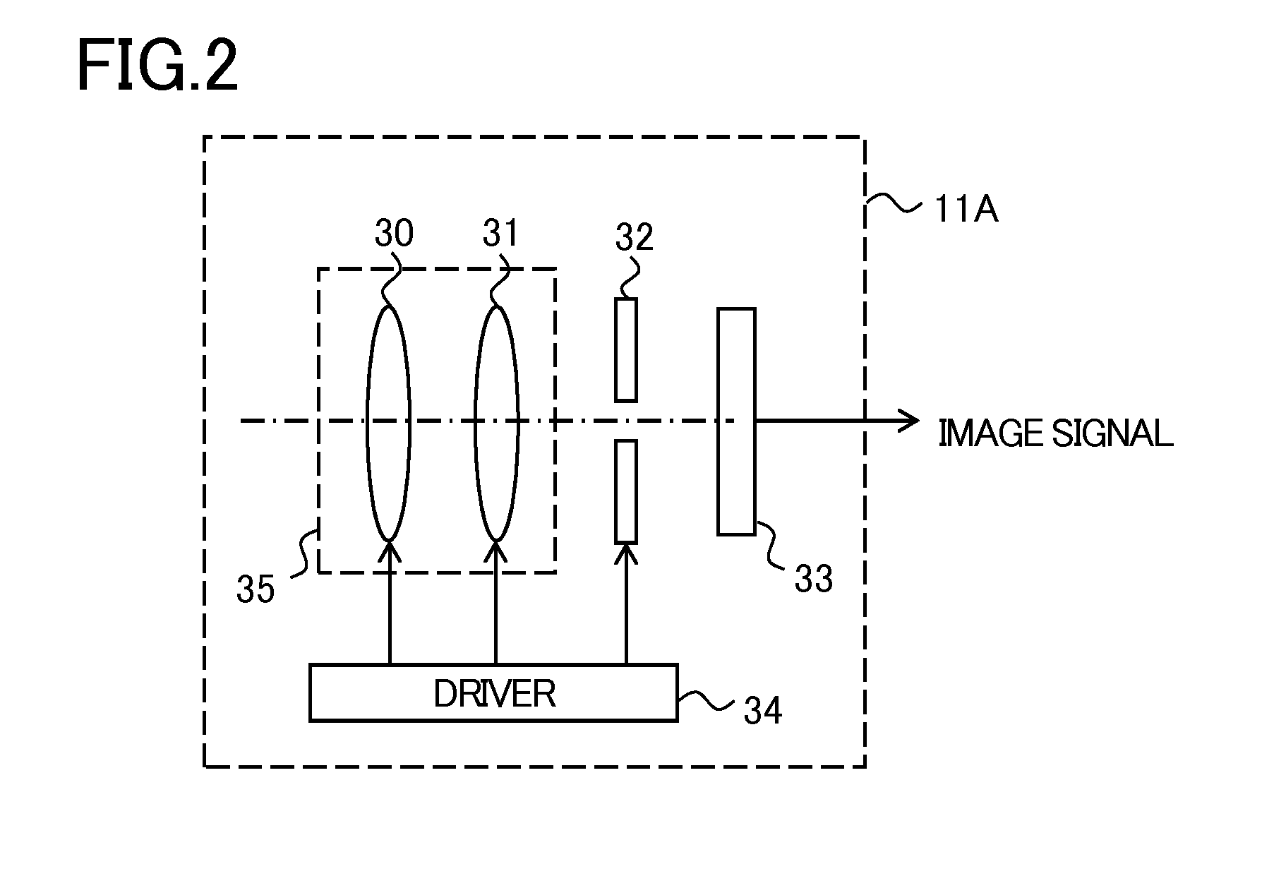
[0023]FIG. 2 is a diagram showing the internal configuration of the image...

second embodiment

[0063]The second embodiment of the present invention will be described. The second embodiment is an embodiment based on the first embodiment; what has been described in the first embodiment can be applied to the second embodiment unless a contradiction arises. In the second embodiment, other image processing that can be performed with the image sensing device 1 will be described.

[0064]FIG. 9 is a block diagram of portions that are particularly involved in the image processing operation of the second embodiment. The focus state adjustment portion 19 of FIG. 9 is the same as in FIG. 1.

[0065]The image sensing portions 11A and 11B form a stereo camera having parallax. Shooting images by the image sensing portions 11A and 11B, which are constituent elements of the stereo camera, are referred to as a left eye image and a right eye image, respectively. The left eye image and the right eye image are shooting images of the common subject. In FIG. 10, images 310 and 320 are examples of the le...


PUM


Abstract

An image sensing device includes: a first image sensing portion that shoots a first image; a second image sensing portion that successively shoots a plurality of second images with focus positions different from each other; a distance information generation portion that generates, based on the second images, distance information on subjects on the first image; and an image processing portion that performs image processing using the distance information on the first image.

Description

CROSS-REFERENCE TO RELATED APPLICATIONS[0001]This nonprovisional application claims priority under 35 U.S.C. §119(a) on Patent Application No. 2011-118719 filed in Japan on May 27, 2011 and Patent Application No. 2012-093143 filed in Japan on Apr. 16, 2012, the entire contents of which are hereby incorporated by reference.BACKGROUND OF THE INVENTION[0002]1. Field of the Invention[0003]The present invention relates to image sensing devices such as a digital still camera and a digital video camera.[0004]2. Description of Related Art[0005]A method of adjusting the focus state of a shooting image by image processing and thereby generating, after the shooting of an image, an image focused on an arbitrary subject is proposed, and one type of processing for realizing this method is also referred to as digital focus.[0006]In the one type of image processing described above, distance information indicating the subject distance of each subject is utilized, and processing for blurring portions...

Claims


Application Information

Patent Timeline
Patent Type & Authority Applications(United States)
IPC IPC(8): H04N5/232G03B13/20
CPCG01S11/12H04N5/23212H04N23/673
Inventor OKADA, SEIJI
Owner SANYO ELECTRIC CO LTD
Why Eureka
Try Eureka