Piezoelectric Generators Having an Inductance Circuit For Munitions Fuzing and the Like
a technology of inductance circuit and munitions fuzing, which is applied in the direction of generator/motor, electric fuze, ammunition fuze, etc., and can solve the problems of requiring the allocation of valuable space, not cost-effective use of reserve batteries for such low power requirements, and affecting the safety of personnel
- Summary
- Abstract
- Description
- Claims
- Application Information
AI Technical Summary
Benefits of technology
Problems solved by technology
Method used
Image
Examples
embodiment 50
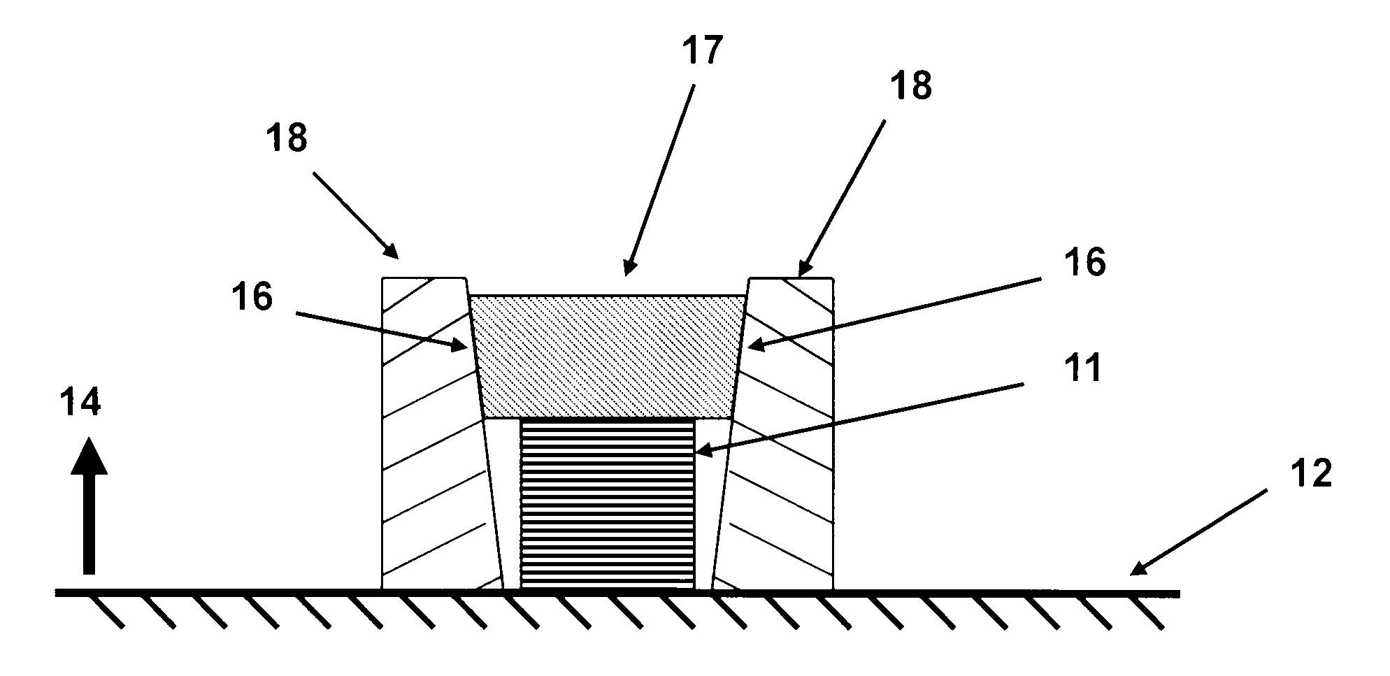
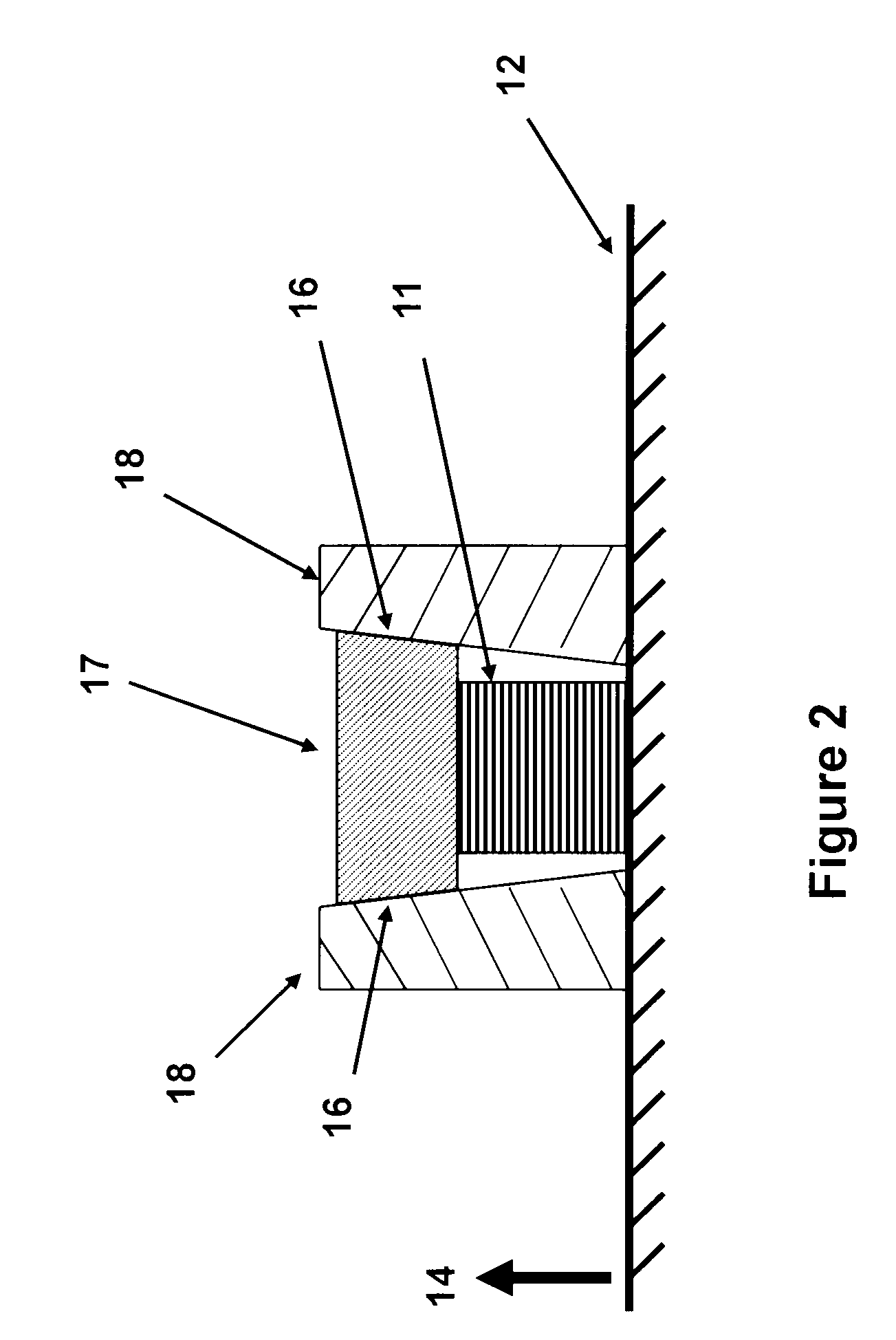
[0050]In general, the position of the traveling wedging element(s) may be exchanged, for example, in the embodiment of FIG. 6, the piezoelectric stack 41 (51 in FIG. 7) and its two sides wedging elements 44 (52 in FIG. 7) may be set against the munitions structure 12 as shown in FIG. 7. In this embodiment 50, the supports 42 (53 in FIG. 7) are then joined together by the relatively rigid backing 54, and positioned as shown in FIG. 7 over the piezoelectric slack assembly. The piezoelectric stack is held against the munitions structure surface 12, but is allowed to expand and / or contract. As the munitions is fired, the acceleration of the munitions in the direction of the arrow 14 would act on the mass of the assembly of the elements 53 and the backing 54, thereby applying a compressive force on the piezoelectric stack 1 via the side wedges 52. With an appropriate wedging angle of the surfaces 55, the assembly of the piezoelectric stack 51 and the blocks 52 is locked in place relative...
embodiment 60
[0052]It is noted that even though in the embodiments shown in FIGS. 2-7 the piezoelectric layers are stacked in planes perpendicular to the direction of the applied compressive loads, the compressive loads may be applied to similar layers stacked in numerous other configurations. For example, in one embodiment 60, the layers 66 may be stacked to form a cone segment 61, which can have an inside hole 62 as shown in the schematic of longitudinal cross-sectional view in FIG. 8a (shown with ring 63). The layers are shown in the top view of piezoelectric element 61 in FIG. 8b (without ring 63). The cone angle is indicated as 65. A ring 63 with a matching inside cone angle is used as the support element attached to the munitions structure 12. During the firing, the firing acceleration in the direction 14 acts on the mass of the piezoelectric element 61, thereby wedging it inside the ring 63. An additional mass 64 may be used to increase the generated compressive force. With an appropriate...
PUM
 Abstract
Description
Claims
Application Information
 - R&D
- Intellectual Property
- Life Sciences
- Materials
- Tech Scout
- Unparalleled Data Quality
- Higher Quality Content
- 60% Fewer Hallucinations
Browse by: Latest US Patents, China's latest patents, Technical Efficacy Thesaurus, Application Domain, Technology Topic, Popular Technical Reports.
© 2025 PatSnap. All rights reserved.Legal|Privacy policy|Modern Slavery Act Transparency Statement|Sitemap|About US| Contact US: help@patsnap.com


