Power line communicaton for electrical fixture control

a technology of power line communication and electrical fixture control, which is applied in the field of electrical circuits, can solve the problems of dimmers that do not work well for light emitting diodes (led) lights, and the implementation of these communication techniques requires a significant financial investment in hardware and infrastructur

Inactive Publication Date: 2009-06-25
CYPRESS SEMICON CORP
View PDF7 Cites 99 Cited by
  • Summary
  • Abstract
  • Description
  • Claims
  • Application Information

AI Technical Summary

Problems solved by technology

Commonly, implementation of these communication techniques requires a significant financial investment in hardware and infrastructure.
Because the switching happens very fast

Method used


Image

  • Power line communicaton for electrical fixture control
  • Power line communicaton for electrical fixture control
  • Power line communicaton for electrical fixture control

Examples


Embodiment Construction

[0009]In the following detailed description, numerous specific details are set forth to provide a thorough understanding of claimed subject matter related to power line communication control for electrical fixtures. However, it will be understood by those skilled in the art that claimed subject matter may be practiced without these specific details. In other instances, well-known methods, procedures, and components have not been described in detail so as not to obscure claimed subject matter.

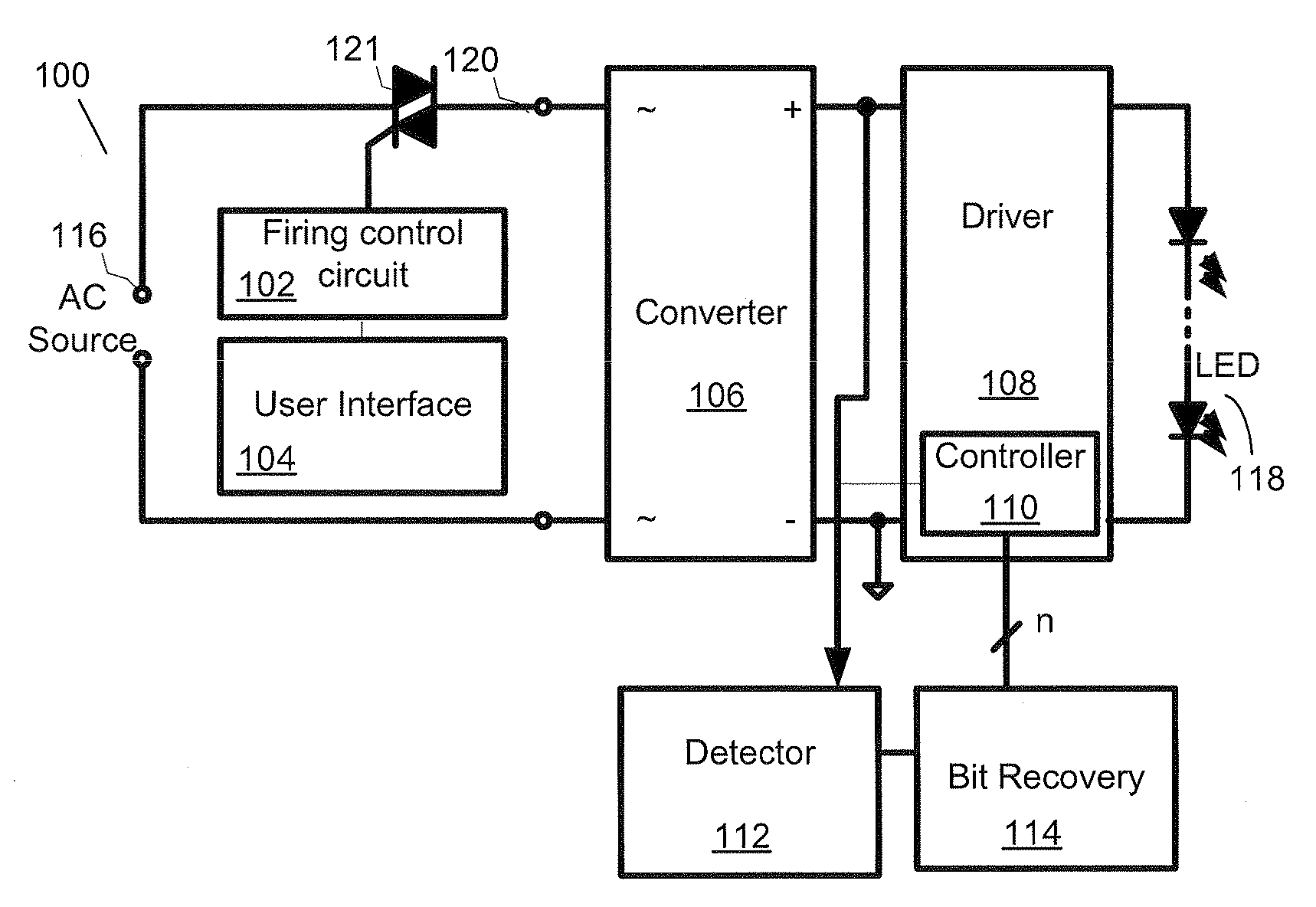
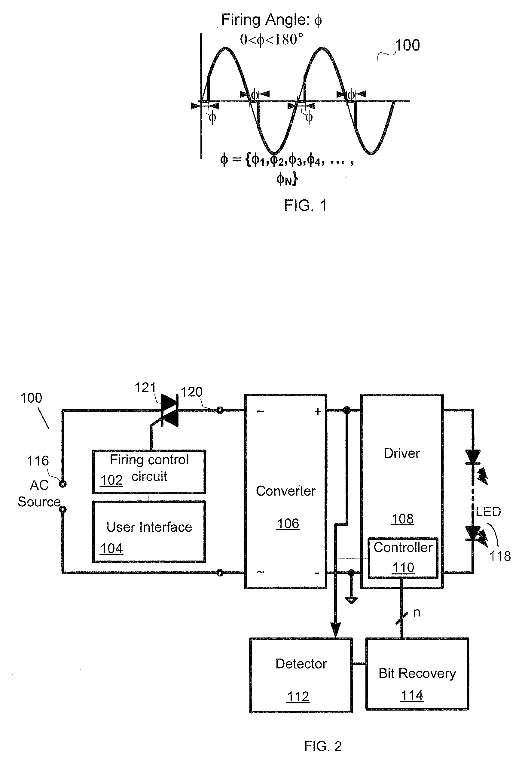
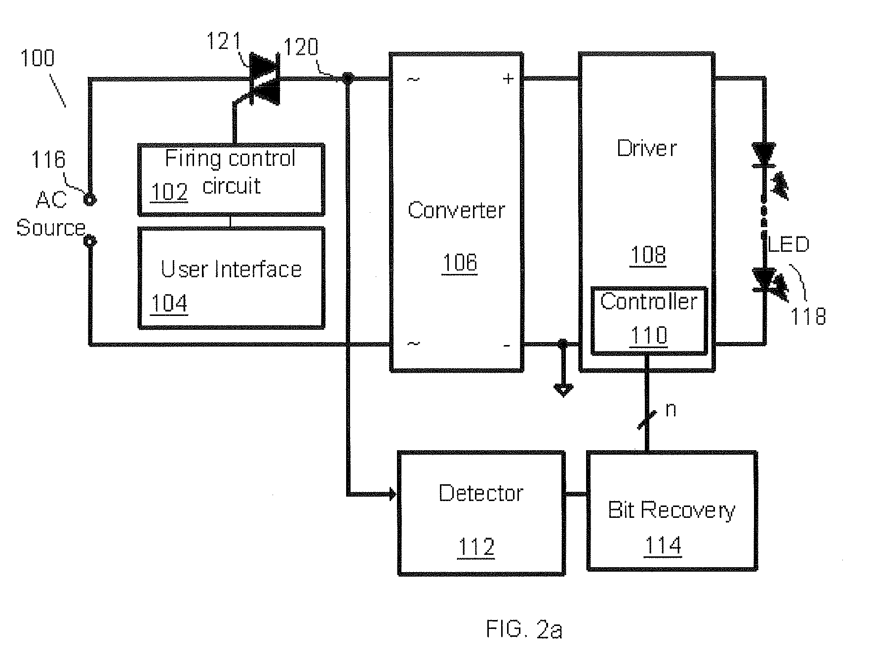
[0010]Disclosed herein is a device and method for communicating control data over a power line to control downstream electrical fixtures. In various embodiments the control data is communicated as firing phase angles on an alternating current (AC). A firing phase angle represents the portion of an AC sine wave “cutoff” by a firing phase angle control circuit. The firing phase angle is controlled by triggering a thyristor coupled to the power line to conduct the AC only at certain points on the A...


PUM


Abstract

We disclose an apparatus capable of receiving control command data for one or more electrical fixtures and modulating an alternating current by modifying firing phase angles to transmit the data corresponding to the control commands via a power line transmitting the alternating current.

Description

RELATED APPLICATIONS[0001]This application claims priority from U.S. Provisional Application No. 61 / 015,702, filed Dec. 21, 2007 and incorporated herein by this reference in its entirety.TECHNICAL FIELD[0002]The present invention relates generally to electronic circuits and in particular to circuits for power line communication.BACKGROUND OF THE INVENTION[0003]Various modes of communication are currently used to control electrical fixtures. Commonly, implementation of these communication techniques requires a significant financial investment in hardware and infrastructure. A classic form of electrical fixture control technology is the thyristor (e.g., TRIode for Alternating Current (Triac)) based dimmer. Such dimmers control the intensity of incandescent bulbs by switching power on and off to the bulb very quickly. Because the switching happens very fast, most people do not detect that the light is flickering. Instead, it appears the bulb is dimmer. Thyristor dimmer circuitry and as...

Claims


Application Information

Patent Timeline
IPC IPC(8): G05B11/01
CPCH04B3/546H04B2203/5408H04B2203/5412H05B37/0263H05B33/0815H05B39/08H04B2203/5458H05B47/185H05B45/31
Inventor GODBOLE, KEDAR
Owner CYPRESS SEMICON CORP
Why Eureka
Try Eureka